3D Printing Design Guidelines
MJF Nylon 12 design rules, process explained, and production tips — the complete Xeon NC reference
Industrial 3D printing at Xeon NC is not desktop printing. Our HP Multi Jet Fusion platform produces engineering-grade Nylon 12 parts with isotropic mechanical properties, production-level tolerances, and no support structures — enabling geometries that simply cannot be manufactured any other way.
This guide covers every design rule you need to prepare parts for our MJF process, from minimum wall thickness and hole sizing to thread inserts and surface finish expectations. Follow these rules and your parts will print correctly, hold tolerance, and arrive ready for assembly.
The Process
- How MJF sintering works
- Layer resolution
- Accuracy & tolerances
- Build volume limits
Design Rules
- Wall thickness minimums
- Overhang & bridge limits
- Hole sizing guidelines
- Thread & insert specs
Materials & Output
- Nylon PA12 properties
- Orientation strategy
- Surface finish options
- File format requirements
How Multi Jet Fusion (MJF) Works
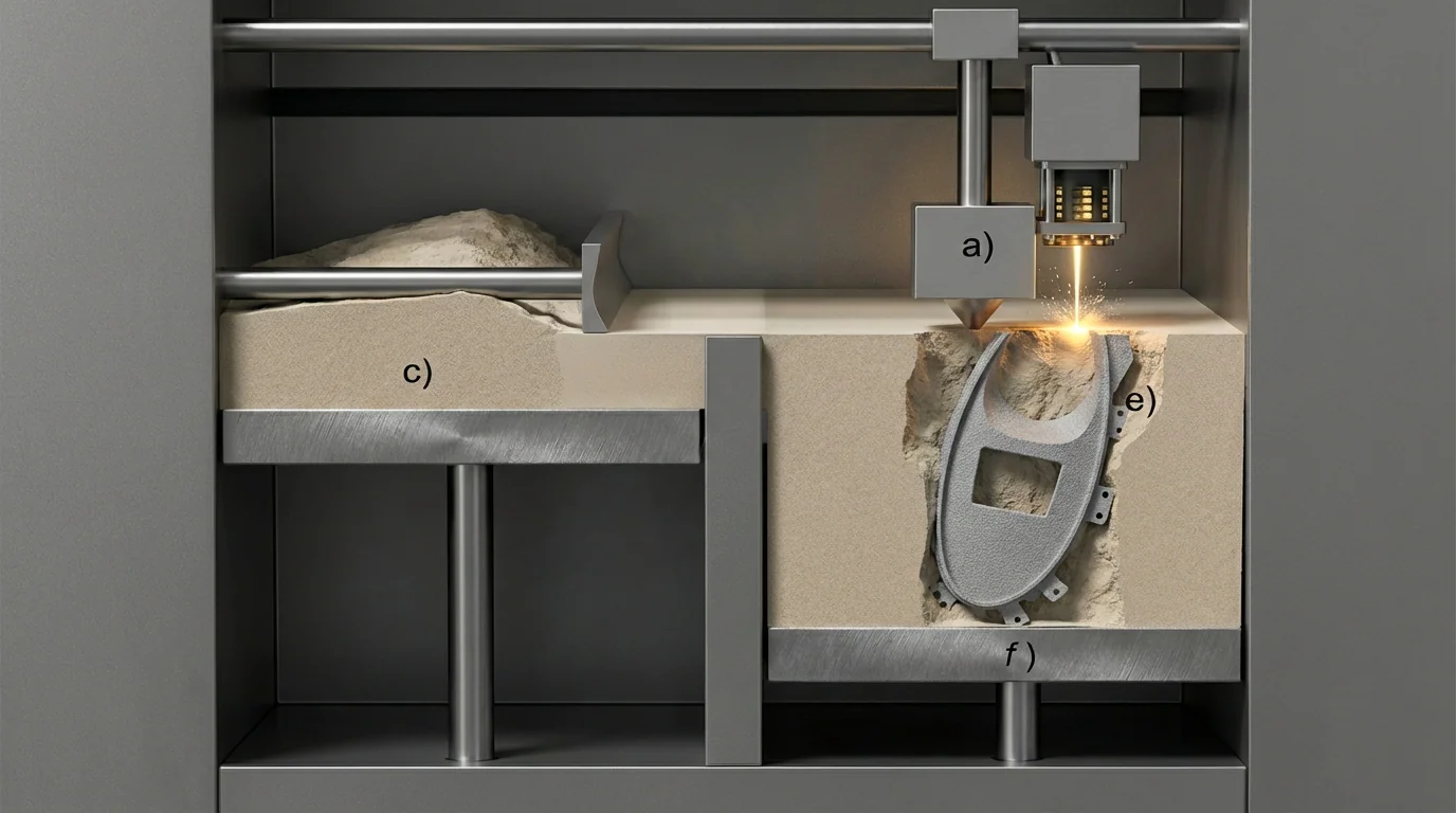
The diagram above is a cross-section of an HP Multi Jet Fusion machine mid-print. Each labeled component plays a critical role in how your part is built.
- a) Fusing Agent Carriage & Thermal Energy Unit: Two carriages sweep back and forth across the build bed. The first carriage jets a liquid fusing agent onto the powder in the exact shape of the current layer slice. On the return pass, an infrared thermal energy lamp fuses only the powder wetted by the agent — areas without agent remain loose powder and act as natural support.
- c) Powder Feed Bed: A reservoir of Nylon PA12 powder sits on the left. A roller sweeps a fresh, precise layer of powder across the build bed after every fused layer — the layer height is typically 0.08 mm (80 microns). This tight layer height produces parts with excellent vertical resolution.
- e) Part Forming in Powder Cake: The part being built is completely buried in loose, unfused powder. This surrounding powder acts as its own support structure — eliminating the need for any external supports, even on extreme overhangs and complex internal geometry.
- f) Build Platform: The platform drops one layer height after each pass, making room for the next layer of fresh powder. The entire block of powder (the "cake") descends together, maintaining thermal uniformity throughout the build.
The Print Process — From File to Part
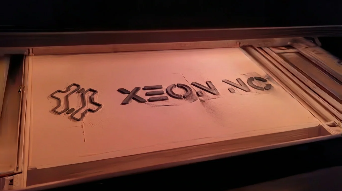
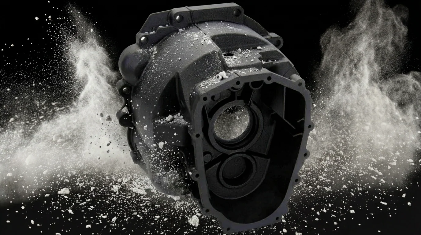
The photo above shows an active HP MJF build bed at Xeon NC. The Xeon NC logo and brand mark are visible as sintered geometry embedded in the powder surface — this is what the part looks like mid-build, before the powder cake has been broken apart and the loose powder removed.
Notice how the sintered regions (dark, fused) contrast sharply with the surrounding loose powder (light). This illustrates the precision of the fusing agent jetting — the HP system can resolve fine text, sharp logos, and intricate geometry within this powder bed.
Step-by-Step Build Sequence
- Step 1 — File Processing: Your .STL, .STEP, or .OBJ file is sliced into 80-micron layers. Optimal build orientation is selected for strength and surface quality.
- Step 2 — Powder Spreading: A fresh layer of Nylon PA12 powder is spread across the build platform at precisely 80 microns thick.
- Step 3 — Agent Jetting: Two print bars jet fusing agent (and optionally detailing agent at boundaries) onto the powder in the pattern of the current layer cross-section.
- Step 4 — Thermal Fusing: An infrared lamp passes over the bed, selectively fusing only the powder wetted by the fusing agent. The entire layer is processed in a single pass — making MJF dramatically faster than SLS laser sintering.
- Step 5 — Repeat: Steps 2–4 repeat for every layer until the part is complete. Build times vary from a few hours to overnight depending on part height and bed density.
- Step 6 — Cooling: The full powder cake must cool slowly and uniformly before extraction. Rushing cooling causes warping. Our HP system manages this automatically with a controlled cool-down cycle.
- Step 7 — Extraction & Depowdering: The cake is broken apart and parts are removed. High-pressure air blasting removes excess powder from surfaces. Parts are then bead-blasted to a uniform matte finish.
- Step 8 — Quality Inspection: Dimensional verification is performed on critical features before shipping.
Accuracy & Tolerances
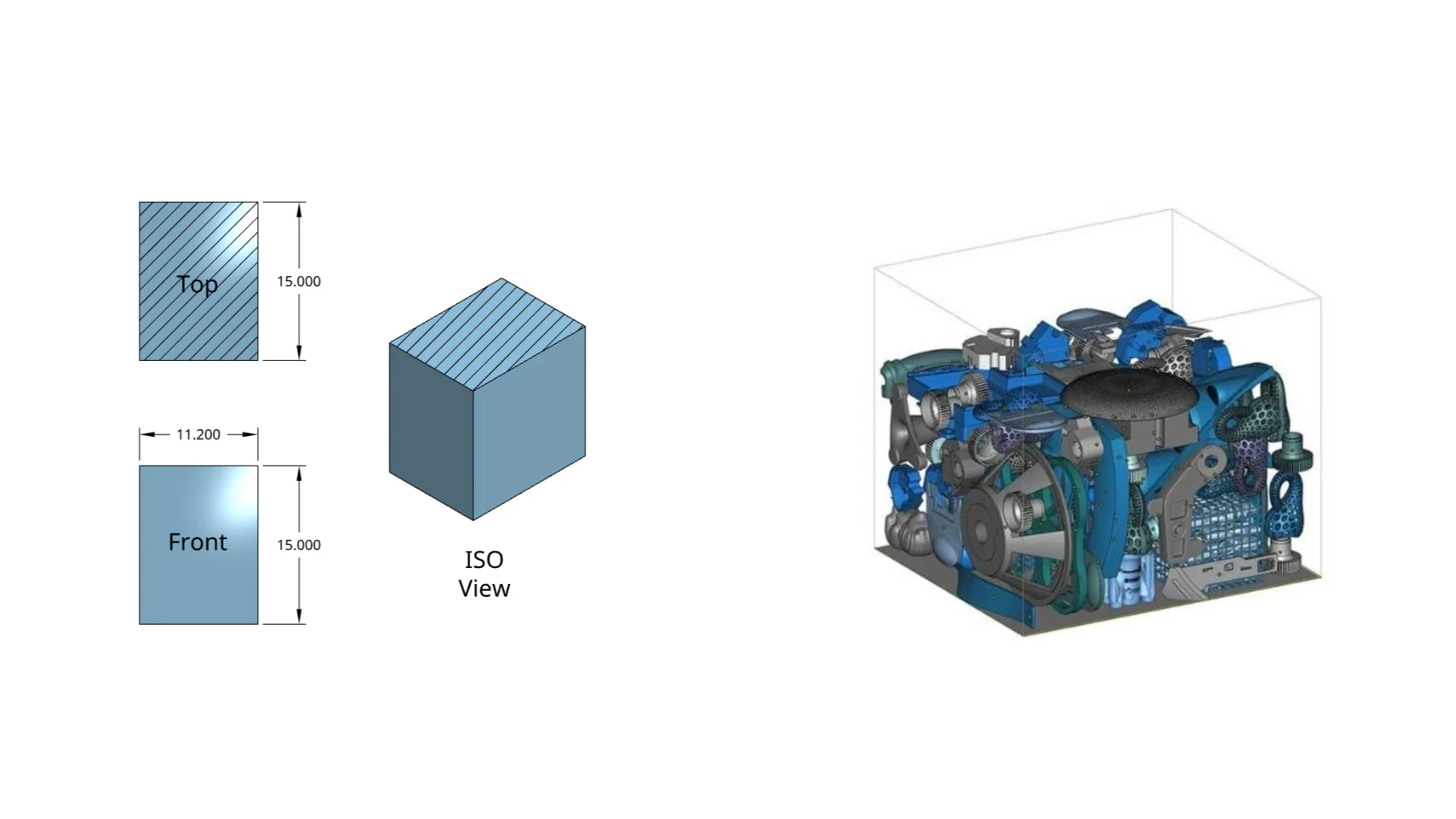
MJF produces consistent, repeatable parts with tolerances suitable for most engineering applications. The diagram above shows the HP 5200 build envelope — 15" × 11.2" × 15" — with a full engine assembly nested inside to illustrate how large and complex parts can be run in a single build.
| Dimension Type | Standard Tolerance | Notes |
|---|---|---|
| Overall part dimensions (XY) | ± 0.2 mm | For parts ≤ 100 mm. Larger parts may see ± 0.3 mm |
| Overall part dimensions (Z / height) | ± 0.3 mm | Z-direction has slightly higher variance due to layer stacking |
| Hole diameters (printed) | ± 0.2 mm | Holes tend to print slightly undersized; use a drill for critical fits |
| Wall thickness | ± 0.2 mm | Thin walls (< 1 mm) may have higher variance |
| Feature resolution (min. printable feature) | 0.5 mm | Features below 0.5 mm may not resolve or may be fragile |
| Layer height | 0.08 mm | Fixed at 80 microns; finer than most FDM processes |
| Spec | Value |
|---|---|
| Max build volume (HP 5200) | 380 × 284 × 380 mm |
| Layer height | 0.08 mm (80 µm) |
| XY Accuracy | ± 0.2 mm |
| Material | Nylon 12 (PA12) |
| Lead time | 1–3 business days |
| Accepted file types | .STL, .STEP, .OBJ |
Wall Thickness
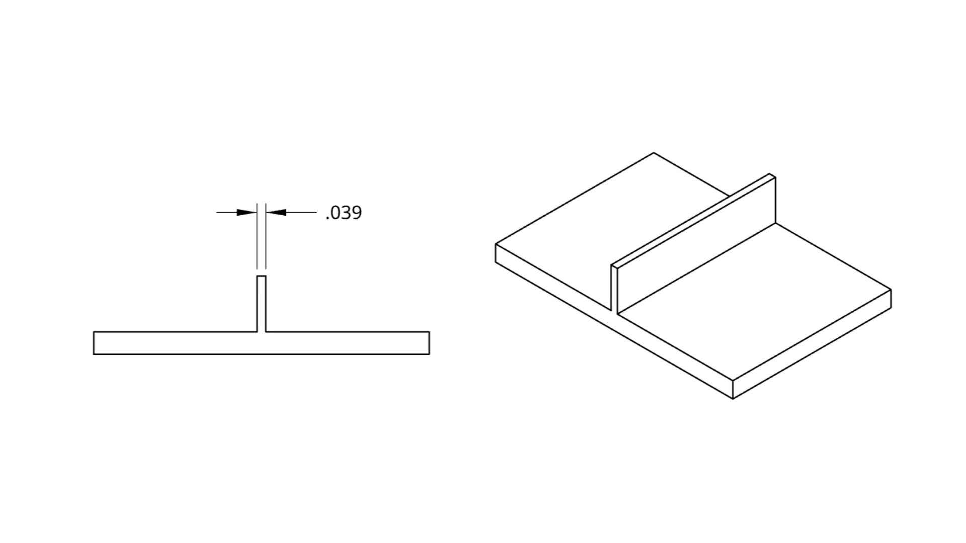
The diagram above shows the minimum printable wall thickness of 0.039" (1.0 mm) shown in cross-section alongside its 3D isometric form. Note how the thin single wall rises from a base plate — below this threshold, the wall will not fully fuse and typically collapses during powder removal. Wall thickness is the single most important design parameter in MJF printing.
| Wall Thickness | Classification | Behavior |
|---|---|---|
| < 0.5 mm | Below minimum | Will not reliably print; likely to collapse during depowdering |
| 0.5 – 0.8 mm | Fragile zone | May print but is flexible and prone to breakage; avoid for structural use |
| 0.8 – 1.5 mm | Minimum recommended | Acceptable for small non-structural features; some flex expected |
| 1.5 – 3.0 mm | Ideal range | Strong, consistent walls for most structural enclosures and brackets |
| > 3.0 mm | Solid / robust | High strength; consider hollowing with internal ribs to save material and cost |
Hollowing Thick Sections
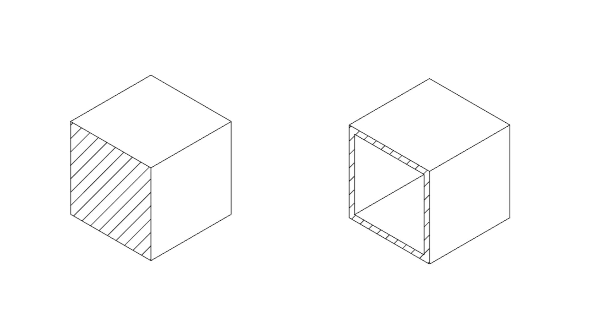
The diagram above shows the two approaches side by side. Left (solid): a fully solid block — high material cost, long print time, risk of internal thermal stress. Right (hollow shell): same external dimensions with a defined wall thickness, dramatically reducing material and build time. Unlike injection molding, MJF does not require uniform wall thickness. For large structural parts, design hollow shells with internal ribs. Always include an escape hole of at least 5 mm diameter so powder evacuates during depowdering.
Overhangs and Bridges
This is where MJF fundamentally outperforms FDM. Because the surrounding loose powder supports the part throughout the build, there is no overhang angle limit in MJF printing. You can design 90° horizontal overhangs, 180° downward-facing surfaces, and fully enclosed cavities — none require support structures.
What "No Supports" Really Means
- Any overhang angle is printable — horizontal ledges, cantilevers, and undercuts all print cleanly without support marks.
- Internal voids and channels print without supports as long as they meet minimum cross-section requirements for powder evacuation.
- Bridging of any span is supported by powder beneath the bridge — but very long thin bridges (> 50 mm unsupported at under 2 mm wall thickness) may sag slightly due to the heat of the fusing step.
Holes and Internal Channels
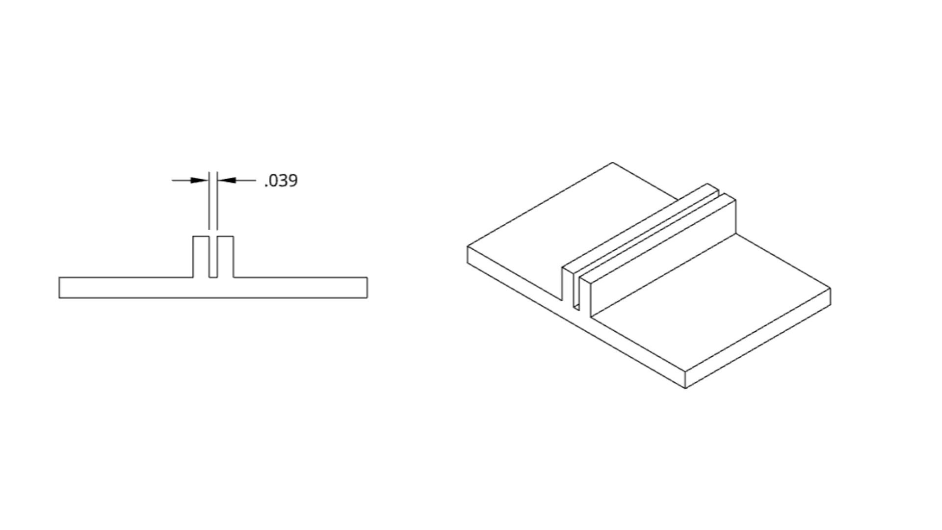
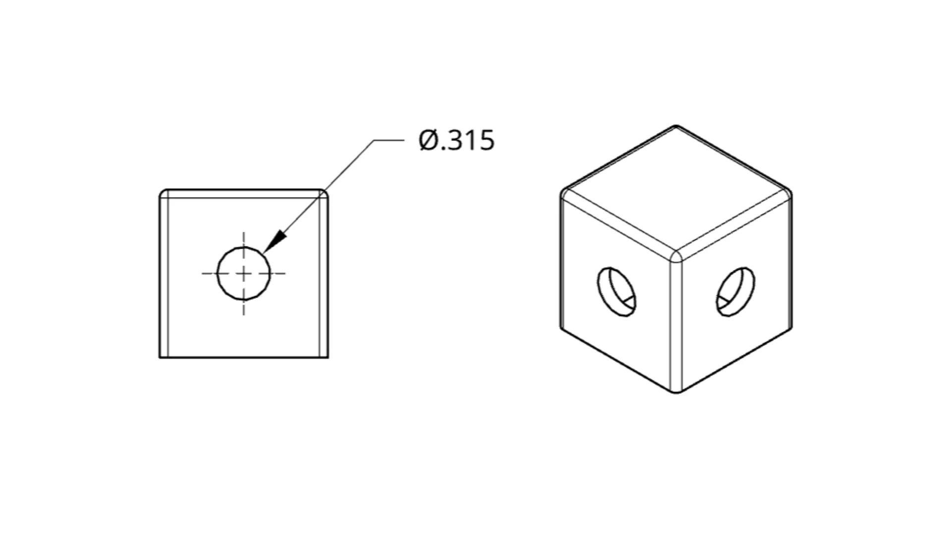
The diagrams above illustrate two critical hole rules. Left: minimum gap or slot width between any two adjacent walls is 0.039" (1.0 mm) — narrower gaps trap unfused powder permanently. Right: minimum printable hole diameter is Ø0.315" (8.0 mm) for horizontal holes — note the isometric view shows oval distortion on the side faces because each layer fuses slightly differently at the top and bottom of a horizontal circular profile.
Vertical Holes (Axis Parallel to Build Direction)
Holes whose axis runs parallel to the Z-axis (vertical in the build chamber) produce the cleanest, most accurate circles. These are the easiest to depowder by gravity.
- Minimum diameter: 1.5 mm for through-holes; 2.0 mm for blind holes (powder must escape)
- For blind holes: Include a small vent hole or flip the part orientation so powder exits by gravity
- Thread preparation: Print at 0.2 – 0.5 mm undersized and tap/drill to final dimension for best thread quality
Horizontal Holes (Axis Perpendicular to Build Direction)
Holes that run horizontally through the part tend to print slightly oval — elongated in the Z-direction — because each layer fuses slightly differently at the top and bottom of the circular profile. For precision bore applications, print undersized and ream or drill to final dimension.
- Minimum diameter: 3.0 mm for horizontal through-holes (smaller holes may not clear powder)
- Roundness: Expect ± 0.2 – 0.3 mm from true round; drill if circularity is critical
Internal Channels for Air, Fluid, or Wire Routing
MJF can print fully enclosed internal channels — one of its most powerful capabilities for conformal design. Follow these rules to ensure channels can be fully depowdered:
// Channels smaller than this trap powder that cannot be extracted
Max. channel length without exit port: ≤ 25 mm
// Longer channels need a mid-point access port or agitation access
Threads and Heat-Set Inserts
Nylon 12 from MJF is strong and durable, but printed threads have lower pull-out and strip-out strength than machined threads in metal — especially under repeated assembly cycles. Understanding when to print threads vs. use hardware inserts is critical for service life.
Printed Threads
Threads can be printed directly into the model but are only recommended for light-duty, infrequent assembly applications (e.g., a lid closed once, a cover panel accessed rarely).
- Minimum thread size: M5 (metric) or #10-32 (imperial) — coarser threads print more reliably than fine-pitch
- Clearance for mating metal screws: Add 0.2 mm extra diameter to the printed thread minor diameter to ensure the metal screw runs smoothly
- Recommended approach: Print a smooth undersized hole and tap with a standard tap after printing for best thread quality
Heat-Set Threaded Inserts (Recommended)
For any application requiring repeated assembly, high pull-out strength, or fine thread pitch, use brass heat-set inserts pressed into a printed boss. This is the industry-standard approach for Nylon 3D-printed parts.
// Slightly undersized; the insert is pressed in with a soldering iron
Boss Wall Thickness ≥ Insert OD × 1.5
// Enough material around insert to prevent cracking during installation
- Installation: Use a soldering iron set to 200–220°C. Press the insert in slowly and straight — Nylon flows around the knurling and re-solidifies, locking the insert permanently.
- Pullout strength: A properly installed M4 brass insert in Nylon PA12 achieves roughly 500–700 N axial pullout — far exceeding a printed M4 thread (~100–180 N).
- Common sizes: M2, M3, M4, M5 — we recommend specifying the insert brand (e.g., McMaster-Carr #94459A) on your drawing so boss sizing can be confirmed.
Clearances and Moving Assemblies
One of MJF's most impressive capabilities is printing assemblies with moving parts in a single build — hinges, gears, living mechanisms — without any assembly step. The surrounding powder separates mating surfaces during the build, and after depowdering the parts move freely.
Clearance for Print-in-Place Mechanisms
| Mechanism Type | Minimum Clearance | Recommended |
|---|---|---|
| Print-in-place hinge (pin/barrel) | 0.4 mm per side | 0.5 – 0.6 mm for reliable free movement |
| Sliding fit (e.g., drawer / rail) | 0.3 mm per side | 0.4 mm for smooth slide without play |
| Snap-fit retention tab | 0.3 mm overlap | 0.4 – 0.5 mm for audible positive snap |
| Meshing gears (printed) | 0.3 mm backlash | 0.4 mm; use Module 1.5+ for tooth strength |
| Press-fit shaft into bore | −0.15 to −0.2 mm | Interference fit; will require mild force to assemble |
Sharp Features, Text, and Fine Detail
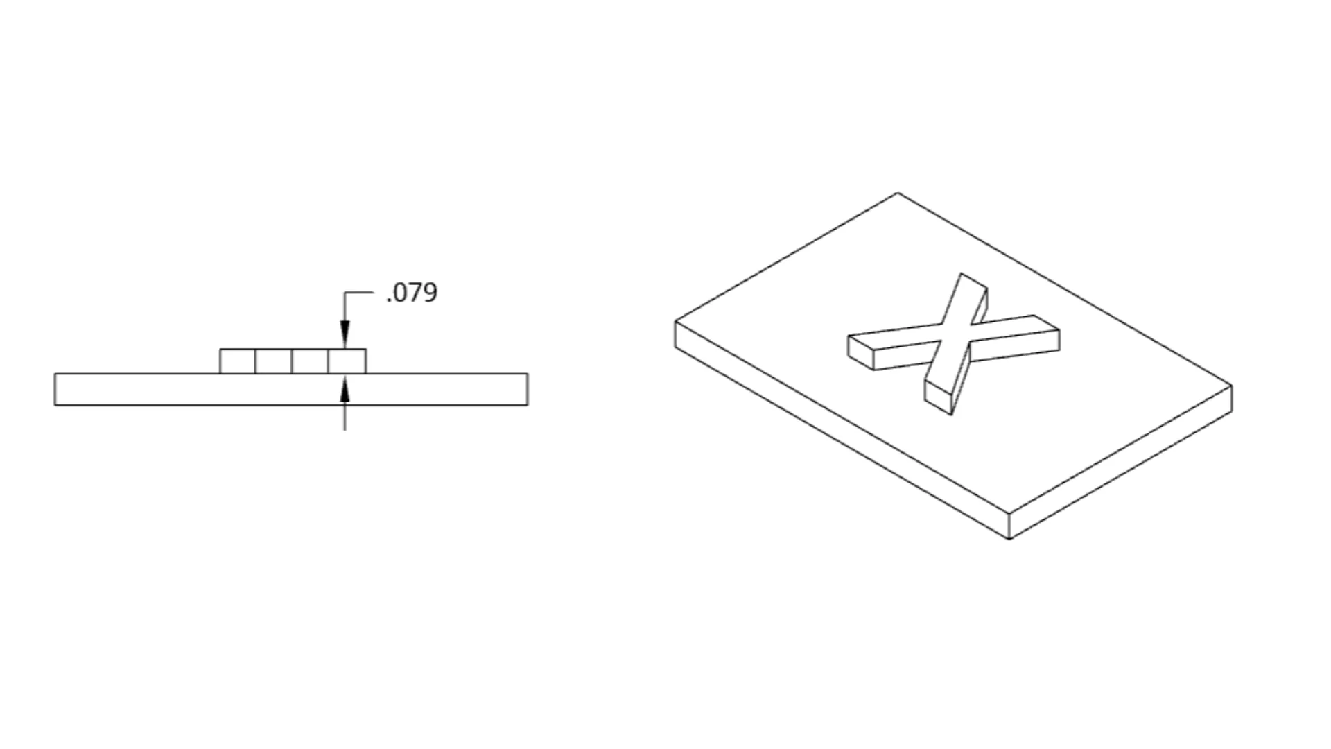
The diagram above shows the minimum embossed feature height of 0.079" (2.0 mm) in cross-section alongside an isometric view of a logo embossed at that height. Below this threshold, fine strokes in letters and thin logo elements may not fully resolve — they fuse partially or appear blurred. MJF's 80-micron layer height delivers impressive detail, but minimum feature heights must be respected for reliable output.
Embossed and Engraved Text
- Minimum embossed text height: 1.0 mm cap height with at least 0.5 mm depth for reliable legibility
- Minimum engraved (recessed) text height: 1.0 mm cap height with at least 0.5 mm recess depth
- Font selection: Bold, sans-serif fonts (Arial Bold, Impact) print more clearly than thin-stroked or serif fonts at small sizes
- Orientation: Orient text surfaces to face upward in the build (perpendicular to Z-axis) for sharpest edge definition
Sharp Edges and Corners
Unlike FDM printing where sharp exterior corners can be printed cleanly, MJF produces a very slight thermal rounding at exterior sharp edges — typically 0.1 – 0.2 mm. For most engineering applications this is inconsequential. If your part has a sealing surface or knife edge that requires a truly sharp edge, specify this on your drawing and we can post-process the edge with a deburring operation.
Minimum Pin and Post Diameter
- Vertical pins (Z-axis): Minimum 1.0 mm diameter — stronger and more reliable than horizontal pins
- Horizontal pins (XY-axis): Minimum 2.0 mm diameter — thinner horizontal features may sag or fracture during depowdering
- Aspect ratio limit: Pin height should not exceed 8× pin diameter without a supporting base or gusset
Interlocking and Multi-Part Assemblies
MJF's build volume (380 × 284 × 380 mm) can nest multiple unique parts in a single build — dramatically reducing per-part cost. Parts from different designs can be printed together as long as they fit within the build envelope.
- Minimum spacing between parts in the nest: 2 mm clearance between any two parts to prevent fusing together during the thermal step
- Gang-printing assemblies: Submit all STL files from an assembly together — we will orient and nest them to maximize build density and minimize your cost
- Identical parts: We can scale quantities within a single build; specify quantity per part number on your order
Nylon PA12 (HP Multi Jet Fusion) — Material Properties
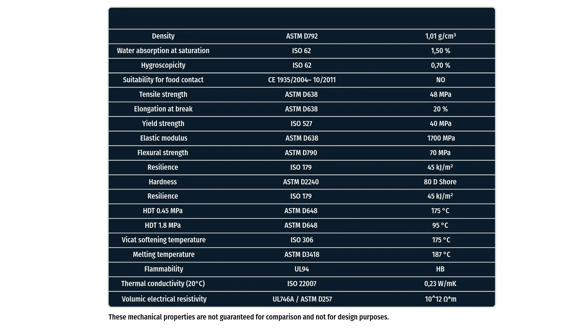
The datasheet above is the official HP Nylon PA12 material specification for MJF. Key values: tensile strength 48 MPa, elastic modulus 1700 MPa, heat deflection temperature 175°C, Shore D hardness 80. Nylon PA12 is chemically the same as injection-molded Nylon 12 — with the added advantage of isotropic mechanical properties meaning strength is consistent in all build directions.
| Property | Value | Test Standard |
|---|---|---|
| Tensile Strength (XY) | 48 MPa | ASTM D638 |
| Tensile Strength (Z) | 45 MPa | ASTM D638 |
| Elongation at Break | 20% | ASTM D638 |
| Flexural Modulus | 1700 MPa | ASTM D790 |
| Impact Strength (Unnotched Charpy) | 54 kJ/m² | ISO 179 |
| Heat Deflection Temperature | 175°C | ISO 75B |
| Density | 1.01 g/cm³ | — |
| Shore D Hardness | 75 | ASTM D2240 |
| Chemical Resistance | Good vs. oils, fuels, most solvents | — |
| UV Resistance | Moderate (degrades with long UV exposure) | — |
Build Orientation
While MJF properties are highly isotropic, build orientation still influences surface texture, dimensional accuracy of specific features, and cost. We select orientation automatically, but understanding the principles helps you design parts that print optimally.
- Cosmetic surfaces: Orient your most visible or critical surfaces so they face upward in the build (top surface in Z). These surfaces receive the most consistent fusing and produce the smoothest texture.
- Precision bores and holes: Vertical holes (axis parallel to Z) maintain roundness better than horizontal holes. If bore circularity is critical, consider redesigning the feature so the hole prints vertically.
- Long, thin parts: Orient slender parts diagonally or vertically to maximize Z-height utilization and reduce potential for thermal warping along a long horizontal axis.
- Tall narrow parts: Very tall narrow geometries (high aspect ratio in Z) can experience slight lean or taper — keep aspect ratio below 10:1 for best results, or contact us for a pre-build review.
Surface Finish
MJF parts have a characteristic matte, slightly granular surface texture from the powder-based process. The standard finish from our process is consistent and uniform — quite different from the layered appearance of FDM and the smoother appearance of SLA.
Standard Finish (Included)
All parts are bead-blasted after depowdering. This removes loose surface powder and produces a uniform, matte gray surface with a surface roughness of approximately Ra 8–12 µm. This finish is suitable for most mechanical and industrial applications.
Dyed / Colored Parts
Because Nylon 12 is naturally gray/off-white from the MJF process, it can be dyed after printing. Black dyeing is the most common option and penetrates the material surface layer for a durable, uniform color. Custom colors are available on request for volume orders.
| Finish Option | Ra Surface Roughness | Availability |
|---|---|---|
| Standard bead blast (matte gray) | ~8–12 µm | Standard — included |
| Black dye | ~8–12 µm | Available on request |
| Vapor smoothing | ~1–3 µm | Available on request — adds lead time |
| Primer + paint | Varies | Available for volume orders |
File Formats and Submission
We accept the following file formats for 3D printing. The closer your file is to clean, watertight geometry, the faster it moves through our system and into the printer.
- .STL Standard triangulated mesh — most common format. Ensure the mesh is watertight (no open surfaces, no non-manifold edges) before exporting.
- .STEP Preferred for parts with complex geometry or tight tolerances. STEP preserves exact NURBS surfaces and loads more accurately than STL.
- .OBJ Accepted for organic geometry, scanned meshes, and sculpted forms. Check for watertight mesh before uploading.
STL Export Best Practices
- Chord tolerance: Export at ≤ 0.01 mm chord height deviation. Coarser exports introduce visible faceting on curved surfaces.
- Units: Confirm your export is in millimeters. If you model in inches, convert before export — file import discrepancies are a common cause of mis-scaled parts.
- Wall check: Run a mesh repair check in your CAD software (Fusion 360, SolidWorks, or free tools like Meshmixer) before uploading. Fix any inverted normals, open surfaces, or overlapping faces.
- Assembly submissions: Submit each part as a separate file. Name files descriptively (e.g., "housing-body-v3.stl") and include a PDF drawing for reference if you have critical dimensions.
Submission Checklist
Before uploading your 3D printing files, verify the following:
✓ Walls ≥ 1.5 mm
All structural walls at or above 1.5 mm. No features below 0.5 mm.
✓ Escape holes
Enclosed hollow sections have at least one 5 mm+ escape hole for powder extraction.
✓ Hole sizing
Horizontal holes ≥ 3 mm. Vertical holes ≥ 1.5 mm. Critical bores spec'd for post-process drilling.
✓ Thread strategy
Heavy-duty threads use heat-set insert bosses. Boss wall = 1.5× insert OD.
✓ Watertight mesh
STL or STEP is watertight with no open surfaces, non-manifold edges, or inverted normals.
✓ Units confirmed
File exported in millimeters. Dimensions verified against drawing before upload.
✓ Clearances set
Print-in-place mechanisms have ≥ 0.4 mm per-side clearance. Snap fits designed to spec.
✓ Material confirmed
Nylon PA12 is appropriate for operating temperature, chemical environment, and load requirements.