01 / Interpret
See manufacturing featuresTurn faces and edges into holes, pockets, bends, flanges, chamfers, and patterns.
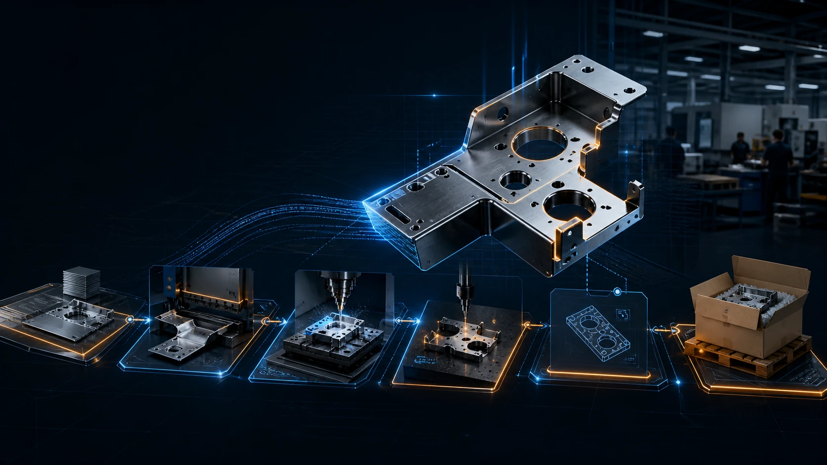
From instant quote to automatic bend simulation, CNC toolpath generation, inspection, and shipping—how geometry becomes the operating language of the smart factory.
Turn faces and edges into holes, pockets, bends, flanges, chamfers, and patterns.
Connect recognized geometry to material, process capability, tooling, and cost rules.
Create proposals for quotes, bend programs, setups, toolpaths, and inspection plans.
Use production and inspection results to improve the next part through the system.
It can become the first executable manufacturing record: geometry that software interprets, prices, plans, checks, routes, measures, and traces.
Traditional manufacturing is full of translation. One person reads the model to estimate material. Another counts holes and bends. A programmer rebuilds manufacturing intent inside CAM. Quality personnel recreate the same geometry in an inspection plan. Shipping receives the part only after production is complete and starts another disconnected workflow.
Every translation consumes time. Every re-entry creates another opportunity to lose context.
CAD feature recognition is one of the technologies that makes that possible. It does not merely display geometry. It asks what the geometry means to a manufacturing system.
A solid model arrives as surfaces, edges, curves, and relationships. Feature recognition groups those elements into forms that quoting and production systems can act on.
Identify uniform thickness, planar faces, open edges, and whether the model can be treated as a sheet-metal body.
Find bend radii, angles, flange lengths, hems, reliefs, and connected faces that may unfold into a flat pattern.
Classify through holes, blind holes, countersinks, counterbores, slots, patterns, and edge proximity.
Recognize pockets, steps, islands, planar faces, profiles, ribs, and other prismatic regions that need operations.
Interpret chamfer width and angle, fillet radius, corner conditions, and whether tooling can reach the geometry.
Find repeated features so one manufacturing rule can be applied consistently rather than programmed feature by feature.
Explore the digital thread below. Each stage reuses the same recognized features, adds new verified information, and passes a richer record downstream.
Validate the solid, establish units and orientation, then interpret geometry as sheet-metal or machinable features. Flag ambiguity instead of forcing a false answer.
NIST describes the digital thread as the connected data that allows model-based definition, manufacturing, and inspection to reuse the same product information. The important word is not digital. It is thread: continuity and traceability across systems that previously operated as islands.
When the system understands the part's features, pricing can move beyond a bounding box and a salesperson's best estimate.
The best instant quote is not a shortcut around process planning. It is process planning compressed into software, with known rules executed immediately and uncertain cases sent to a person.
Recognized bends and flanges allow software to propose the flat pattern, tooling, bend sequence, handling orientation, and NC program against a specific machine environment.
TRUMPF states that TecZone Bend can create an automatic program proposal from 2D and 3D data, including the NC program, with automatic tool suggestions and real-time collision checking. That is the operating model: the geometry is recognized, matched to a real tooling library, sequenced, and simulated.
Feature-based CAM can recognize machinable shapes and apply repeatable shop rules for how those shapes should be made.
SOLIDWORKS CAM describes automatic feature recognition for holes, pockets, bosses, and other prismatic forms, then uses knowledge-based machining to assign strategies and tools. Autodesk likewise documents feature recognition that extracts manufacturing features and operations from solid or surface models to create toolpaths.
Automatic toolpaths are most valuable for familiar, repeatable features. Complex surfaces, difficult workholding, high-consequence materials, tight geometric tolerances, and unusual access still demand experienced programming and machining judgment.
A connected system carries part identity and requirements through production, measures the result against the same definition, then closes the order with traceable logistics.
Connect revision, material lot, process plan, machine, operator or automation cell, setup, program, and completion status to the specific part.
Record actual cycle time, tool life, bend correction, machine events, nonconformance, scrap, rework, and approved deviations.
Use CAD geometry, PMI, drawings, and the inspection plan to create measurement routines and compare as-built results with requirements.
Associate inspection reports, material certifications, finish records, first-article documents, photos, and approvals with the order.
Use completed quantity, part mass, dimensions, finish sensitivity, packaging rules, destination, and promised date to select and document shipment.
Feed actual time, inspection trends, tool performance, packaging results, and exceptions back into costing and process rules.
The future is not merely automatic inspection programming or an automatic shipping label. It is the ability to prove which revision was made, from which material, by which process, against which requirements, with which result, and where it went.
Confidence without evidence is not automation. It is hidden risk.
Standard materials, familiar features, supported tolerances, proven tooling, validated postprocessors, and repeatable inspection logic can move quickly.
Ambiguous holes, unusual bends, conflicting metadata, incomplete drawings, novel workholding, or low-confidence recognition should pause for applications engineering.
New programs, tight capability requirements, safety-critical parts, regulated documentation, and special processes need explicit release and validation.
Actual production and inspection data should improve estimates and recommendations only through controlled, reviewable changes.
Machines matter. The system that turns customer intent into validated machine action will matter just as much.
NIST's digital-thread research points toward well-structured 3D product definitions that communicate with manufacturing and quality systems, with inspection results feeding back to engineering. That vision is not one perfect file format or one omniscient algorithm. It is an interoperable operating model.
At Xeon NC, the direction is clear: make the path from CAD to a real part increasingly direct, visible, and intelligent—while preserving the human expertise needed to release work responsibly.
It is the software process of interpreting geometry as manufacturing-relevant features such as holes, pockets, slots, bosses, bends, flanges, chamfers, and patterns rather than treating the model only as faces and edges.
It can supply geometry-derived inputs such as size, volume, cut length, bend count, hole types, pocket volume, and likely process steps. A reliable quote also needs material, quantity, tolerance, finish, certification, inspection, lead-time, and other requirements.
Modern systems can use 2D or 3D data to propose tooling, bend sequence, collision checks, and NC programs. The result still must be validated against the actual material, tooling library, machine, tolerances, handling, and production requirements.
Yes. Feature-based CAM can apply rules for operations, tools, and toolpaths. A qualified programmer still validates workholding, setup orientation, access, feeds and speeds, collisions, postprocessing, and part requirements.
Usually not. Material, tolerances, surface finish, threads, heat treatment, coatings, weld requirements, inspection, certifications, cosmetic criteria, packaging, and intended function may require PMI, a drawing, configuration choices, notes, or direct review.
No. It shifts people away from repeated translation and toward validation, exception handling, process improvement, and high-consequence decisions.
Yes. Upload a supported CAD file and ask for applications-engineering review when geometry, tolerances, material, finish, certifications, or the production strategy need human attention.
This article describes an industry direction and supported examples of current software capability. It does not claim that every part, process, or requirement can move through a fully unattended workflow today.
Upload your supported model for an instant quote. Add the drawing and project requirements when tolerances, finishes, certifications, inspection, or other manufacturing details control the part.
Upload Parts & Get a Quote