Countersinking for Sheet Metal and CNC Parts
A Xeon NC Engineering Brief
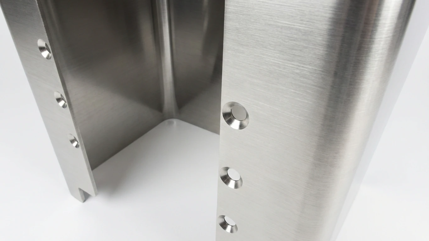
Flush fasteners are not a cosmetic detail. They are a mechanical interface choice that affects assembly repeatability, surface safety, coating outcomes, and long-term joint stability.
Countersinking is the controlled creation of a conical seat that allows a flat-head fastener to sit flush (or slightly below flush) with the part surface. Done correctly, it improves fit, reduces snag risk, and tightens stack-up behavior across multi-part assemblies.
Why countersink at all
Countersinking is most valuable when you need a flat exterior surface and reliable alignment at assembly. Common drivers:
- Enclosures and panels: no protrusions; improved handling and packaging.
- Consumer-facing hardware: clean surfaces; consistent visual finish.
- Fixtures and machine plates: predictable fastener seating; fewer assembly surprises.
- Multi-part stack-ups: self-centering seat improves registration under torque.
What countersinking changes mechanically
A countersink does three things at once:
Creates a wedge interface
The angled seat converts axial clamp load into both axial and radial components. That increases contact area vs. a pan-head on a flat surface and can reduce loosening risk when properly designed.
Adds a self-centering constraint
Flat-head screws “seek center” as they seat. This can improve alignment in real assemblies—but it can also fight intentional clearance if you designed the hole for float.
Removes load-bearing material near the surface
This is the trade. Too deep = reduced net section, edge breakout risk, and higher chance of distortion in thin stock.
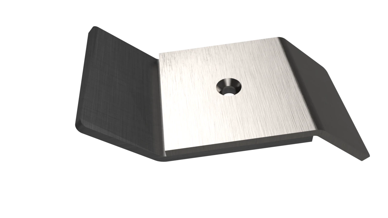
Key benefits (the ones that matter in production)
Flush surface, fewer failure modes
- Reduces snag points and handling damage
- Improves gasket contact and panel mating
- Less interference with adjacent components
Better assembly repeatability
- Self-centering seat reduces “shift” during torque
- Helps keep hole-to-hole misalignment from turning into scrap
Better durability at the interface
- Recessed heads resist impact and abrasion
- More stable seating surface than an unprepared chamfer
The real drawbacks (and when you should not countersink)
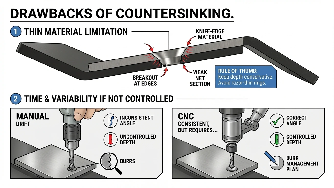
1) Thin material limitation
Countersinks require thickness. If you don’t have enough, you end up with:
- knife-edge material at the top
- breakout at edges
- weak net section around the hole
2) Time and variability if not controlled
Manual countersinking introduces drift across parts. CNC-controlled countersinking is consistent, but you still need:
- correct angle
- controlled depth
- burr management plan
Choosing the countersink angle
Most designs should treat angle as fastener-standard driven:
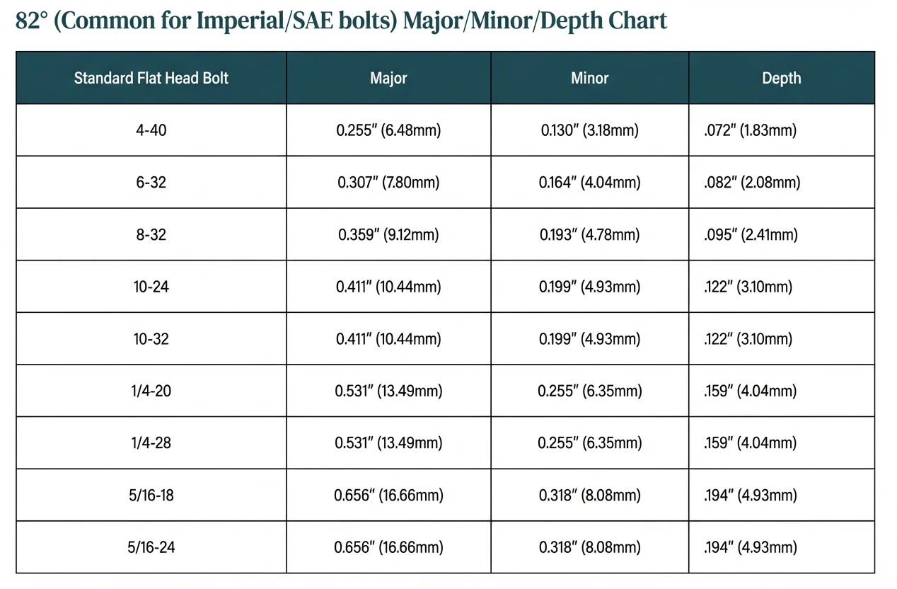
- 82° common for imperial flat-head screws
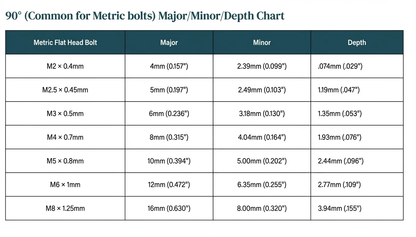
- 90° common for metric flat-head screws
- 100° useful when you want shallower depth in limited thickness
- 120° specialty use (often rivets/aerospace conventions)

Standard Countersinks Available at Xeon NC
Review the standard countersink sizes and dimensions available for quoting and manufacturing your parts.
Imperial Series
Metric Series
CAD and drawing: how to specify countersinks correctly
In 3D CAD
Model the pilot/minor hole and apply a countersink feature:
- specify angle
- specify major diameter (or depth)
- call out the fastener standard when possible
In 2D drawings (recommended even for 3D uploads)
Use a standard callout format, for example:
or
5.0 THRU, CSK 10.0 x 90°