Understanding Laser Kerf
A Xeon NC Process Guide on cut width, toolpath offsets, and dimensional accuracy
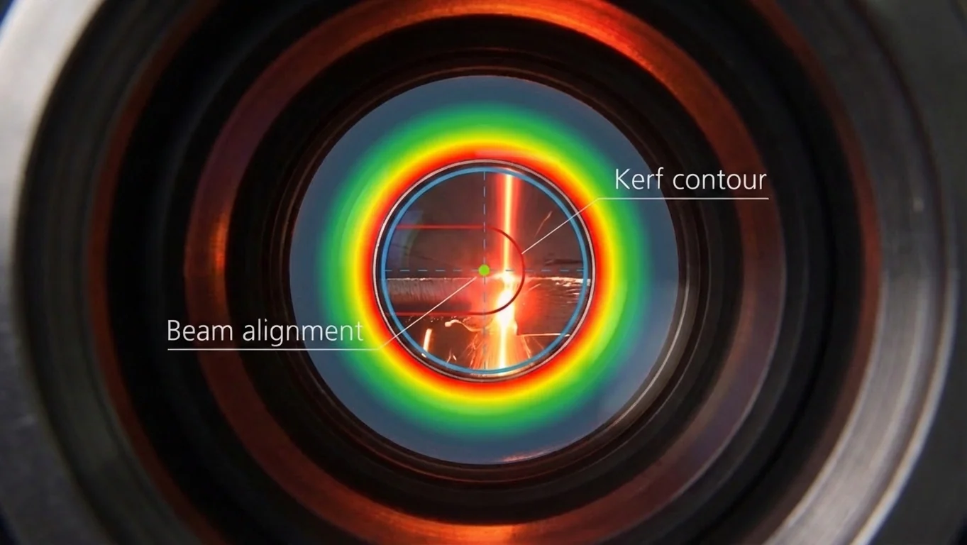
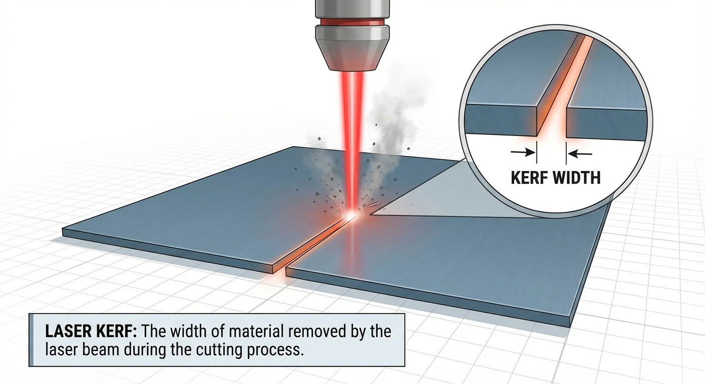
Even though a laser beam is highly focused light, it is not infinitely thin. As it slices through metal, it vaporizes a very narrow channel of material to separate the part from the sheet.
This physical gap—the material that disappears during the cut—is called the Kerf. While it may only measure fractions of a millimeter, failing to account for kerf in high-precision manufacturing means holes will end up too large and profiles will end up too small.
At Xeon NC, our TRUMPF laser software automatically calculates and offsets the cut to account for this gap, ensuring your parts match your CAD dimensions perfectly. This guide explains how kerf works and how it affects sheet metal design.
Kerf Offset and Toolpath Compensation
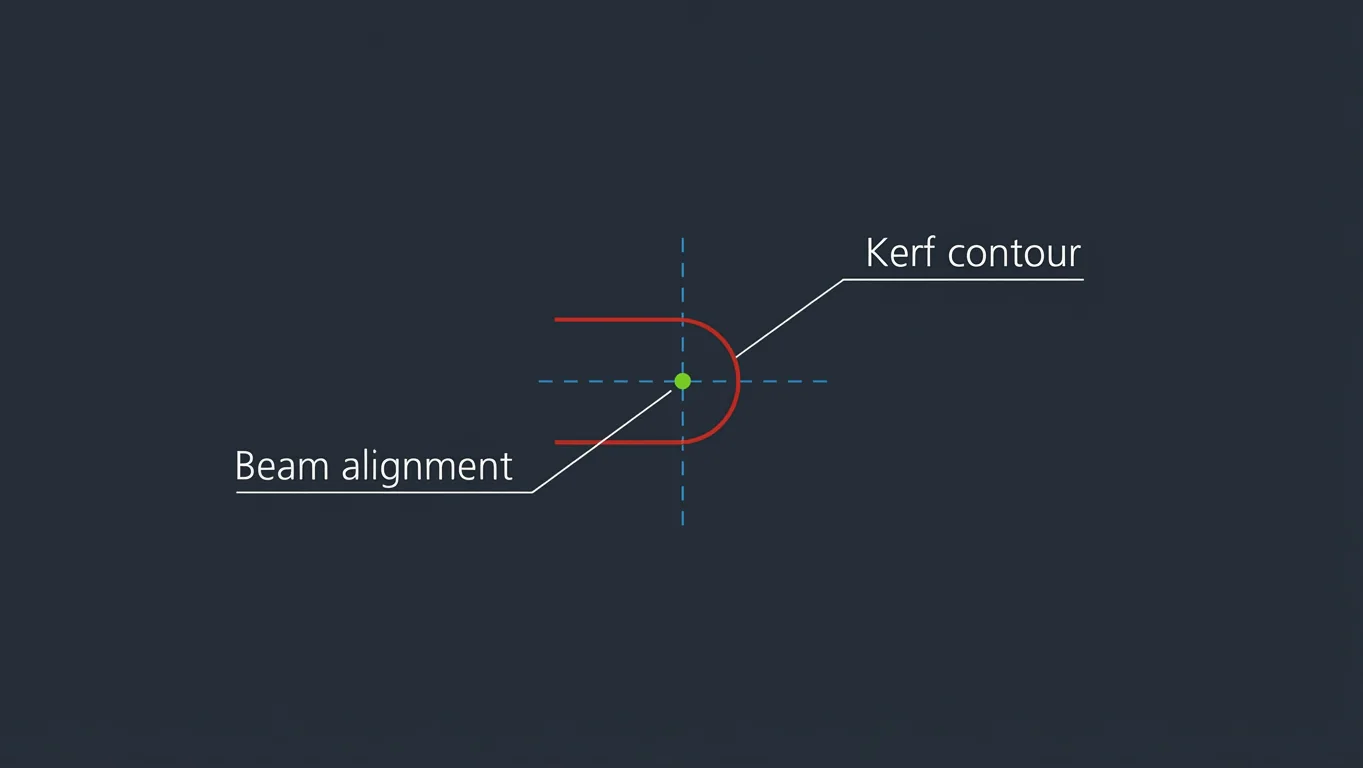
If the machine simply drove the exact center of the laser beam dead along the CAD line, half of the beam would burn into the part, and half would burn into the scrap. If the kerf was 0.008 inches wide, the final part would be 0.004 inches undersized on every single edge.
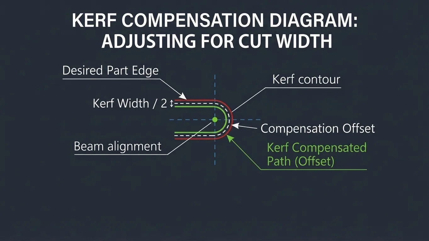
To avoid this, we use Kerf Compensation (also called Toolpath Offset).
- Outside Profiles: The software automatically shifts the center of the laser beam outward by exactly half the kerf width, preserving the CAD profile's external dimension.
- Inside Profiles (Holes/Slots): The software shifts the center of the laser beam inward (towards the scrap slug) by half the kerf width, ensuring the hole diameter remains true to nominal specs.
Because of this automated processing, you should never offset or scale your 3D CAD models to "compensate" for the laser. Draw parts exactly to the dimension you need them.
How thickness changes the Kerf width
Kerf width is not a static number. It actively changes depending on four primary variables: material type, material thickness, laser power, and focal length.
When cutting thin sheet metal (such as 0.060" aluminum), the laser energy focuses to a razor-sharp point, maintaining a very narrow, highly concentrated kerf width.
However, as material gauge increases, the laser requires entirely different optic parameters. To blast through half-inch steel plate, the machine must run a broader focal beam and rely on higher assist gas pressure or intense oxygen reactions. This results in a dramatically wider kerf gap.
Essential Design Rules for Kerf
When engineering designs for laser processing, understanding kerf translates to three critical rules:
- Never pre-compensate CAD: Draw your DXF, STEP, or exact geometry exactly as you want it physically measured upon receipt. If you draw it 10.000", we will configure the kerf offset to yield a 10.000" part.
- Mind the minimum hole size: A general rule of thumb across the industry dictates that the minimum hole diameter should be at least equal to the material thickness (a 1:1 ratio). Attempting to burn a 0.050" hole in 0.250" plate creates intense thermal blowout because the kerf consumes the entire core.
- Slot width constraints: Similar to holes, long slots should be wider than the material thickness to allow proper kerf clearance and molten metal evacuation without slag buildup bridging the gap.
Kerf is also what sets the clearance in an interlocking joint: a tab slot is oversized by the kerf plus 0.004″ so the parts still assemble after compensation. The Slot & Tab Size Chart works that out for every gauge we stock, alongside the minimum slot width at each thickness.