Now accepting custom orders — Get your instant quote →

Why Laser-Cut Parts Warp

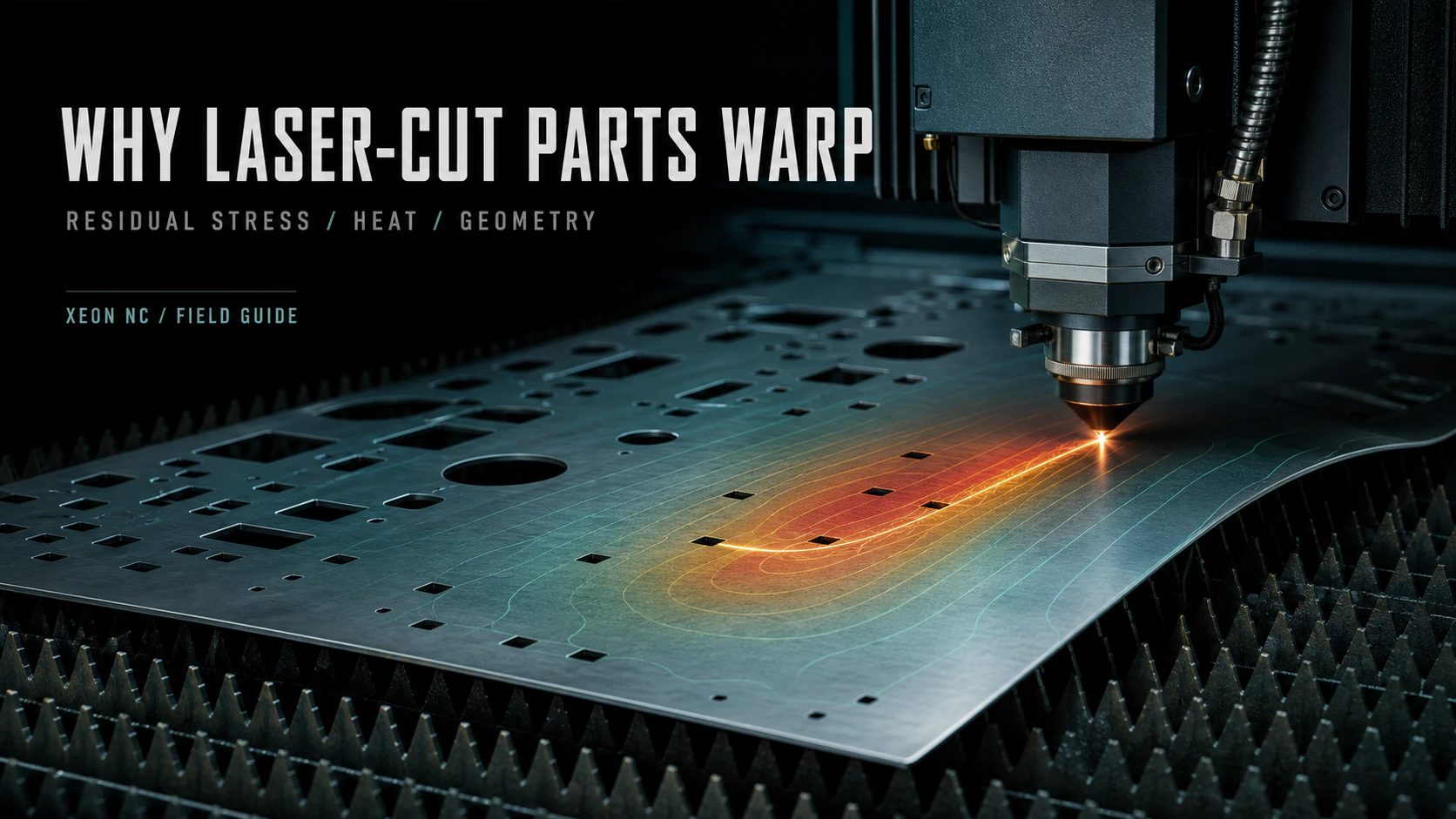
Thin sheet metal bowing upward during fiber laser cutting with a technical heat and stress overlay

Distortion is not random. It is evidence of an unbalanced system: stress already in the sheet, heat moving through the cut, or geometry losing the stiffness that kept it flat.

Laser Cutting Field Guide
Distortion / DFM / Process
10 minute read
01 / MATERIAL

Stress arrives in the sheet

Rolling, leveling, cooling, and prior processing can leave a flat sheet in a balanced but stressed condition.
02 / HEAT

The kerf creates a gradient

Localized expansion and contraction can become visible when heat accumulates faster than it can dissipate.

03 / GEOMETRY

Cutting removes stiffness

Long strips, narrow webs, and perforated panels have less section left to resist stress redistribution.

04 / STRATEGY

Sequence changes the result

Cut order, spacing, retention, and cooling time can influence where the sheet moves and when.

←  Back to all guides
01 / Define the failure mode

Warping is unwanted shape change.

A part intended to stay flat may bow, twist, curl at an edge, or develop a shallow oil-can shape after cutting.

The important word is unwanted. Sheet metal is expected to move during a planned bend. Warping is movement outside the design intent. It can be temporary, disappearing when a part is restrained in an assembly, or permanent, remaining after external force is removed.

Laser cutting is often blamed because the movement becomes visible during or immediately after the cut. But the laser is not always the original source of the stress. It may simply release or redistribute what was already present in the sheet.

The cut does not need to create all the stress. It only needs to disturb the balance.
Warping and the heat-affected zone are not the same thing.

The HAZ is the narrow region near a thermally cut edge whose properties may be altered by the thermal cycle. Warping is a larger-scale change in part shape. Heat can contribute to both, but one does not prove the other.

02 / Three interacting mechanisms

The sheet, the heat, and the geometry.

Most laser-cut distortion can be understood as an interaction between three systems rather than one isolated cause.

01 / INHERITED

Residual stress

Sheet can carry locked-in stress from casting, rolling, coiling, leveling, heat treatment, and straightening. It looks flat because those stresses are in equilibrium. Cut away material and the remaining section may seek a new shape.

02 / INTRODUCED

Thermal stress

The laser heats a narrow moving zone. Nearby metal expands and then contracts as it cools. If the path is dense, slow, or concentrated in one region, the uneven thermal cycle can create or amplify distortion.

03 / REVEALED

Lost stiffness

Cutouts, narrow webs, and released perimeters reduce the section resisting movement. The same stress state that a solid panel could contain may visibly move a thin, open, or slender part.
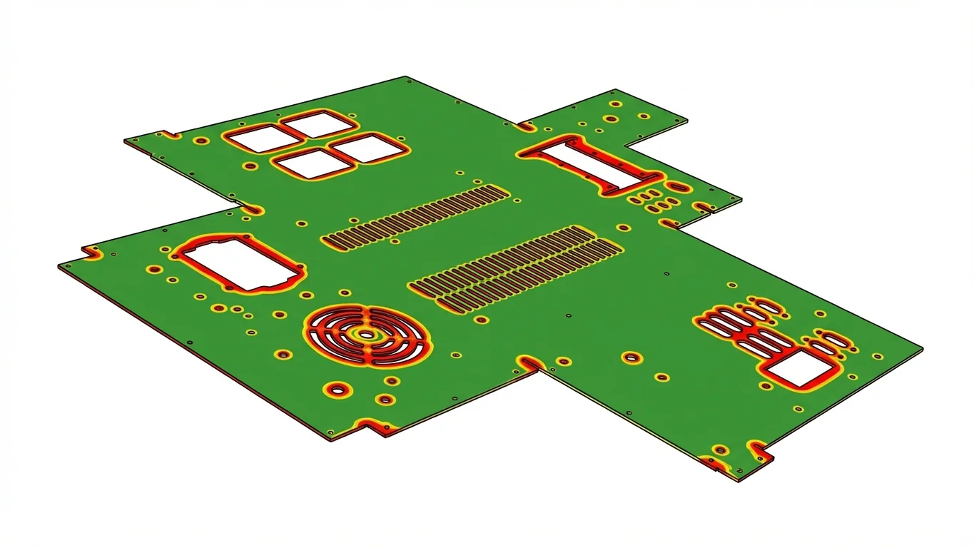
Technical illustration showing heat concentrated around laser-cut edges and dense feature patterns
Local heat, global consequence.Each kerf is narrow, but dense features can place many thermal cycles into one area while simultaneously removing the material that gave the panel stiffness.

Mechanical force can add a fourth mechanism. Thin or delicate parts may distort while tabs are broken, parts are lifted from the nest, or aggressive flattening is attempted. That is why a useful review follows the part beyond the laser path.

03 / Read the geometry

Risk lives in patterns, not a single number.

There is no universal percentage of removed area that guarantees a flat part or guarantees a warped one.

Open area matters, but so do sheet thickness, material condition, part aspect ratio, feature density, perimeter continuity, cut sequence, and how symmetrically material is removed. A compact 50% open part may behave better than a long strip with far less material removed.

Geometry signal
Why risk increases
First design response
Long, narrow part
Low transverse stiffness lets residual stress produce bow or twist along the length.
Widen the section, increase thickness, or leave temporary carrier material for review.
Dense perforation field
Many short cuts concentrate thermal cycles while removing continuous load paths.
Spread features, widen ligaments, and avoid clustering the entire cut length in one zone.
Large flat panel
Wide unsupported area can oil-can even when total displacement is shallow.
Add a flange, rib, bead, return, or assembly support where function allows.
One-sided cutouts
Asymmetric material removal changes stiffness and stress release across the part.
Balance the pattern or preserve a wider continuous frame around the weaker side.
Narrow webs
Thin connections heat quickly, cool quickly, and have little bending stiffness.
Increase web width, shorten unsupported length, or add more connections.
Thin stock
Bending stiffness falls rapidly as thickness decreases.
Evaluate the next gauge, especially when flatness is functional rather than cosmetic.

For a flat strip of the same material and width, bending stiffness scales approximately with the cube of thickness. A modest gauge increase can therefore change the distortion response far more than its weight increase suggests.

04 / Screen the design

Run a quick warping preflight.

This tool does not predict a flatness tolerance. It flags combinations that deserve closer DFM review before production.

// Geometry risk screen

Warping preflight

Heuristic only. Material condition, nesting, parameters, and actual dimensions still control the result.
Screening resultModerate
Review cut density and feature balance. Consider wider webs or a formed stiffening feature, and identify the actual flatness requirement on the drawing.
05 / What the shop controls

Cut strategy can manage risk, not repeal physics.

The production team controls how energy and restraint move through the nest.
01
Qualified parameters
Power, speed, focus, assist gas, and pierce strategy should achieve a stable cut without unnecessary energy input.
02
Cut sequence
Internal features are generally completed before the outside contour, and dense work can be sequenced to avoid loading one local zone continuously.
03
Heat distribution
Jumping between separated regions or allowing brief cooling intervals can reduce accumulation on patterns with unusually high local cut length.
04
Part retention
Microjoints or tabs may keep vulnerable parts registered in the sheet until cutting is complete, but removal must be planned so denesting does not create a new deformation.
05
Nesting and orientation
Spacing, grain direction where relevant, shared heat zones, and where the outer profile releases all influence the local boundary conditions.
06
Material review
Incoming flatness can be inspected, but a flat sheet may still contain residual stress that becomes visible only after material is removed.
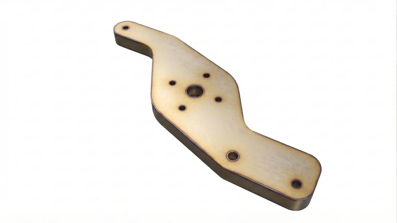
Example part showing a wider visible heat-tint zone after regular thermal cutting
More visible thermal reachHeat tint is not a direct measurement of warp, but it makes the location and relative reach of the thermal cycle visible.
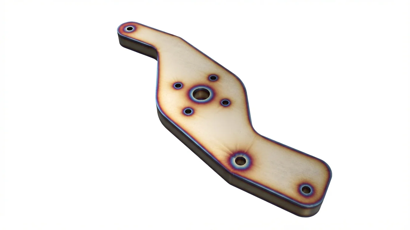
Example part showing a narrower visible heat-tint zone with a cooled cutting process
More concentrated thermal reachSpecialized cooling and qualified parameters can manage heat input for appropriate materials and thicknesses.

Published experiments on 1 mm stainless sheet have shown that cut sequence can influence both the magnitude and direction of base-sheet deformation. Other work on laser processing of thin aluminum and steel has found that breaks, jump speed, clamping, and heat-dissipating support can change thermal distortion. Those findings reinforce a central point: the path through the work matters.

06 / What the designer controls

Make flatness part of the geometry.

The strongest fix is often not a slower laser. It is a part that has enough structure to remain stable.
01
Preserve load paths
Keep continuous frames, widen narrow ligaments, and avoid cutting every stiffness path into disconnected islands.
02
Distribute the pattern
Spread dense features where function allows and avoid concentrating the longest cumulative cut path in one small region.
03
Add formed stiffness
A flange, return, rib, or bead can increase stability dramatically compared with an otherwise identical flat panel.
04
Revisit thickness
When flatness is functional, moving to the next gauge may be more robust than attempting to control a highly flexible panel through process alone.
05
Balance material removal
More symmetric mass and stiffness distribution reduces the tendency for one side to become the preferred direction of movement.
06
Define the requirement
State where flatness matters, how the part is supported during inspection, and whether assembly restraint is part of the functional condition.
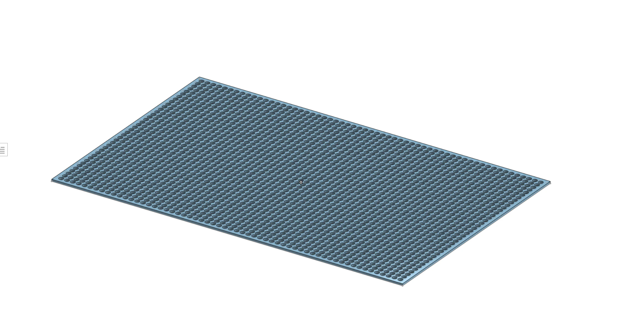
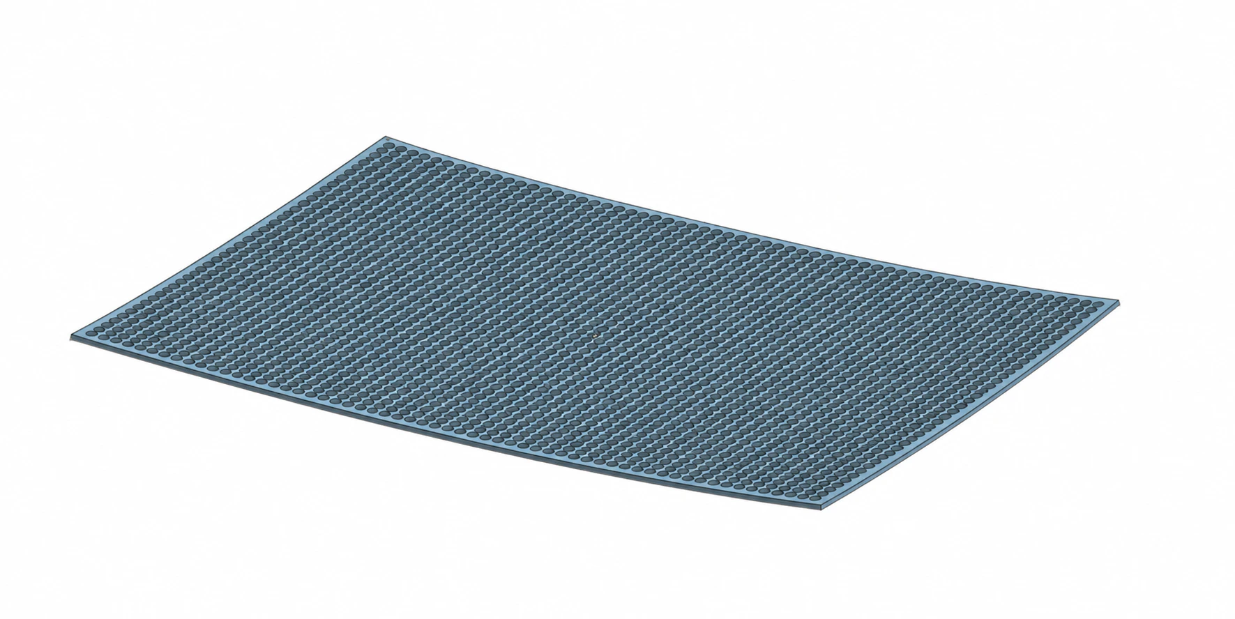
Visual balance is not the same as structural stiffness. The material left between the holes must carry the stress.
Flat CAD model of a sheet-metal panel with a dense, evenly spaced perforation pattern
01 / CAD — nominally flatThe hole field is balanced and the outer perimeter is continuous. The model communicates ideal geometry, but it does not show the residual stress in the incoming sheet or the stiffness lost during cutting.
Warped state of the same densely perforated sheet-metal panel, bowed through its center
02 / Released state — bowedThousands of holes create a long concentrated cut path and leave only narrow ligaments. As the sheet is released, those thin webs cannot keep the original stress state flat, so the panel finds a new curved equilibrium.

The perimeter stayed continuous. The panel still moved. The frame and uniform pattern help, but they cannot replace the bending stiffness removed from the center field. For a panel like this, the design review should consider wider ligaments, fewer or smaller holes, a wider border, greater thickness, or a formed flange, rib, or bead.

Do not solve an undefined problem.

“Must be perfectly flat” is not an inspection plan. Define the datum, supported or free-state condition, tolerance zone, and the assembly function that the requirement protects.

07 / After the cut

A warped part is not automatically a failed part.

Disposition depends on severity, material, finish, downstream operations, and what the assembly actually requires.

Mild bow may disappear when a panel is fastened to a rigid frame. Some parts can be leveled or carefully corrected. Others should not be forced because straightening can move holes, mark a finished surface, change the local stress state, or create problems for a later bend.

Severe lift during cutting is also a process risk. A released edge or center can approach the nozzle, interfere with height control, or prevent a safe continuation of the program. Distortion can also make automated deburring or surface finishing unreliable because those processes expect stable contact with a reasonably flat workpiece.

The right question is not “did it move?” It is “does the final condition protect function?”
Review before release

Send the geometry, not a guess.

Upload your CAD for an instant quote, then include flatness, assembly, and cosmetic requirements in the notes for applications review.

Upload Parts & Get a Quote
08 / FAQs and engineering sources

Warping, answered.

Why do laser-cut sheet-metal parts warp?

Warping occurs when the stress state through a part becomes unbalanced. The imbalance can come from residual stress already in the sheet, uneven heating and cooling during cutting, loss of stiffness as material is removed, or mechanical force during handling and denesting.

Does laser cutting always create enough heat to warp a part?

No. Fiber laser cutting is fast and localized, but thin sheet, dense local cut paths, low-stiffness geometry, and certain material conditions can still convert a localized thermal cycle into visible distortion.

Which material warps the most?

There is no single ranking that controls every geometry. Thermal conductivity, thermal expansion, yield strength, temper, rolling history, thickness, and residual stress all matter. Review the specific alloy and part rather than relying on a universal material hierarchy.

Can cut sequence really change distortion?

Yes. Experimental work on thin stainless sheet has demonstrated that cutting sequence can change the direction and amount of sheet deformation. Sequence is one control, not a guarantee, because incoming stress and part geometry still matter.

Can a warped part be flattened?

Sometimes. Mild distortion may disappear in assembly or respond to controlled leveling. Severe distortion can affect dimensions, finish, downstream bending, or deburring, so the correction method must be reviewed against the part requirements.

Engineering sources

  1. Nunobiki, Okuda, and Yoshida, Study of Influence of Laser Cutting Sequence upon Thermal Deformation of a Base Sheet, Journal of Advanced Mechanical Design, Systems, and Manufacturing.
  2. Arif, Yilbas, and Abdul Aleem, Laser cutting of thick sheet metals: Residual stress analysis, Optics & Laser Technology.
  3. Wortmann, Brosda, and Olowinsky, Evaluation of measures to reduce thermal distortion caused by laser-based structuring of thin aluminum and steel sheets, Fraunhofer ILT.
  4. Szymański et al., Measurement of residual stresses in hot-rolled steel sheets for laser cutting, Computer Methods in Materials Science.
DFM before the first cut

Control the risk.
Build the part.

Upload the CAD, identify where flatness matters, and let the geometry and production path be reviewed together.

Start an Instant Quote