Fiber Laser Cutting Design Guide
The complete Xeon NC reference for designing production-ready flat parts
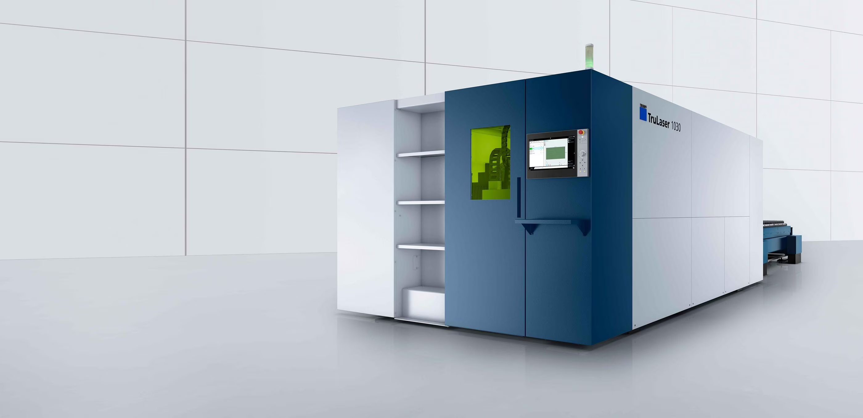
This guide covers every design rule and practical constraint you need to prepare your flat parts for our TRUMPF fiber laser systems. From minimum hole diameters to file format requirements, this is the single reference document for submitting files with zero back-and-forth.
If you follow the guidelines on this page, your parts will be quoted faster, cut cleaner, and arrive exactly as your CAD model specifies.
Accepted File Formats
We accept 2D vector geometry in industry-standard formats. The closer your file is to clean, production-ready geometry, the faster it moves through our system.
Accepted formats
- DXF required for flat 2D sheet metal profiles
- STEP / STP required for 3D models with bends or formed features
File preparation rules
- Single closed contour: Every cut profile must be a fully closed polyline or spline. Open endpoints produce invalid geometry.
- No duplicate lines: Stacked or overlapping geometry causes the laser to cut the same path twice, damaging the edge.
- No construction layers: Remove dimensions, notes, center marks, and hatching from the cut geometry layer.
- Units: Confirm your DXF is saved in inches or millimeters—not a unitless drawing.
Standard Tolerances
At Xeon NC, our standard tolerance capability covers most production scenarios without additional cost or special setup.
| Dimension Type | Standard Tolerance | Notes |
|---|---|---|
| Profile dimensions | ± 0.005″ | Outer contours and internal cutouts |
| Hole diameters | ± 0.005″ | Circular features; kerf-compensated |
| Hole-to-hole spacing | ± 0.005″ | Center-to-center distances |
| Edge-to-hole | ± 0.005″ | Hole center to nearest edge |
| Flatness | Per material | Sheet flatness is stock-dependent; thin gauges may exhibit minor bow |
Minimum Feature Sizes
Laser cutting has physical limits governed by beam diameter, kerf width, and material thickness. Designing below these dimensional floors risks burning, poor edge quality, or physical inability to separate the feature from the sheet.
Minimum hole diameter
The minimum hole that can be cleanly cut is generally equal to the material thickness (1:1 ratio). Cutting a hole smaller than the sheet thickness causes the beam to dwell too long in a small area, resulting in thermal blowout and a rough slug.
| Material Thickness | Min. Hole Diameter | Recommendation |
|---|---|---|
| 0.030″ – 0.060″ | ≥ 0.030″ | Clean cut; small pierce mark possible |
| 0.060″ – 0.125″ | ≥ 1× thickness | Ideal 1.5× for cleanest edges |
| 0.125″ – 0.250″ | ≥ 1× thickness | Pierce strategy changes; may see witness mark |
| 0.250″ – 0.500″ | ≥ 1.5× thickness | Wider kerf; thermal accumulation at pierces |
Minimum slot width
Slot width rules mirror hole diameter constraints. As a general floor, slot width should never be less than material thickness. Narrower slots risk slag bridging and incomplete evacuation.
Minimum web / bridge width
The minimum solid material remaining between two adjacent cuts (the "web") should be at least equal to material thickness. Thinner webs warp, melt, or fall into the slat bed during processing.
Corners and Internal Radii
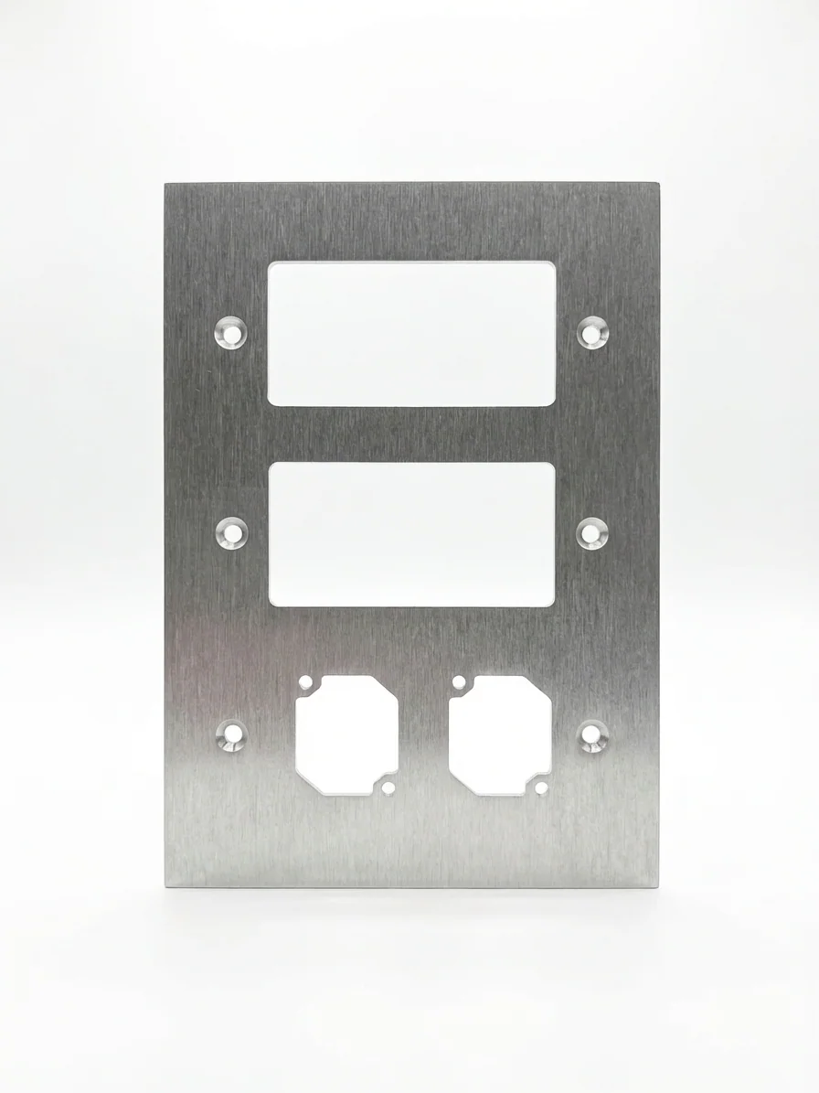
A laser beam has a physical diameter. This means that every internal corner will inherently carry a small radius—the beam simply cannot cut a mathematically perfect 90° interior angle.
Practical radius guidance
- Thin gauge internal corners will carry approximately a 0.010″ – 0.015″ natural radius
- Mid gauge internal corners will carry approximately a 0.015″ – 0.025″ natural radius
- Thick plate internal corners will carry approximately a 0.025″ – 0.040″ natural radius
If your design requires a genuinely sharp internal corner for mating or assembly, consider adding a small relief cut (sometimes called a "mouse ear" or "bone" relief) at the corner. This prevents stress concentration and gives the beam a defined termination point.
Tab-and-Slot Design
Tab-and-slot joints are one of the most popular self-fixturing strategies in laser-cut assemblies. They align parts for welding or fastening and dramatically reduce assembly time.
- Tab width: Minimum 2× material thickness. Narrower tabs deform during insertion.
- Slot clearance: Add 0.005″ – 0.010″ total clearance per side for a press-fit alignment, or 0.010″ – 0.020″ for easy-slide assembly.
- Tab length: Minimum 3× material thickness to provide adequate shear surface for welded joints.
- Corner relief: Add small radii or relief notches at the base of internal slot corners to avoid stress risers and match the natural beam radius.
For the worked numbers at your gauge — tab width, tab length, slot width and height, and the clearance for each fit, all drawn to scale — see the Slot & Tab Size Chart. Every clearance there is stated as total clearance between the tab and the slot wall.
Text and Engraving
Laser cutting can produce text, logos, and part markings directly on the sheet in two ways:
Through-cut text
Letters are fully cut through the sheet. This works well for signage and decorative panels, but small fonts and narrow strokes break apart. Minimum recommended font height for through-cut lettering is 0.250″ (6 mm) with a stroke width no less than material thickness.
Engraved / etched text
The laser marks the surface without cutting through. This is ideal for part numbers, revision markings, and serial identifiers. Engraved text can go significantly smaller—down to approximately 0.100″ (2.5 mm) font height.
Nesting and Gang-Sheet Strategies
XeonNC2.webp)
After your geometry is validated, it is nested onto a standard sheet size. Nesting is the algorithmic process of arranging parts to maximize material utilization while maintaining cut quality and skeleton stability.
What we optimize for
- Material utilization: Higher nest efficiency means less waste and lower per-part cost.
- Cut sequence: The order in which parts are cut affects heat distribution and skeleton rigidity.
- Common-line cutting: Where appropriate, adjacent parts share a single cut line, eliminating redundant passes.
- Microtabs: Small retaining bridges can be added to prevent small parts from tipping into the slat bed during cutting.
Material Capabilities
Our fiber laser platform processes the following sheet metals with production-grade edge quality:
| Material | Max. Thickness | Typical Assist Gas |
|---|---|---|
| Mild / Carbon Steel | 0.750″ | Oxygen or Nitrogen |
| Stainless Steel (304, 316, 430) | 0.500″ | Nitrogen (oxide-free edge) |
| Aluminum (5052, 6061, 3003) | 0.500″ | Nitrogen |
| Galvanized Steel | 0.250″ | Nitrogen or Compressed Air |
| Copper / Brass | 0.125″ | Nitrogen |
For alloys or thicknesses not listed above, contact our engineering team for a feasibility review.
Submission Checklist
Before uploading your files, verify the following:
✓ File format
DXF or STEP format only
✓ Closed contours
All profiles are fully closed polylines with no open endpoints
✓ No duplicates
Zero overlapping or stacked lines on the cut layer
✓ Text outlined
All text converted to curves before export
✓ Dimensions specified
Units confirmed (inches or mm); no unitless drawings
✓ Material & qty
Material type, alloy, thickness, and quantity clearly stated