Sheet Metal Design Guidelines
Key terms, concepts, and design rules for bending and laser cutting — the complete Xeon NC reference
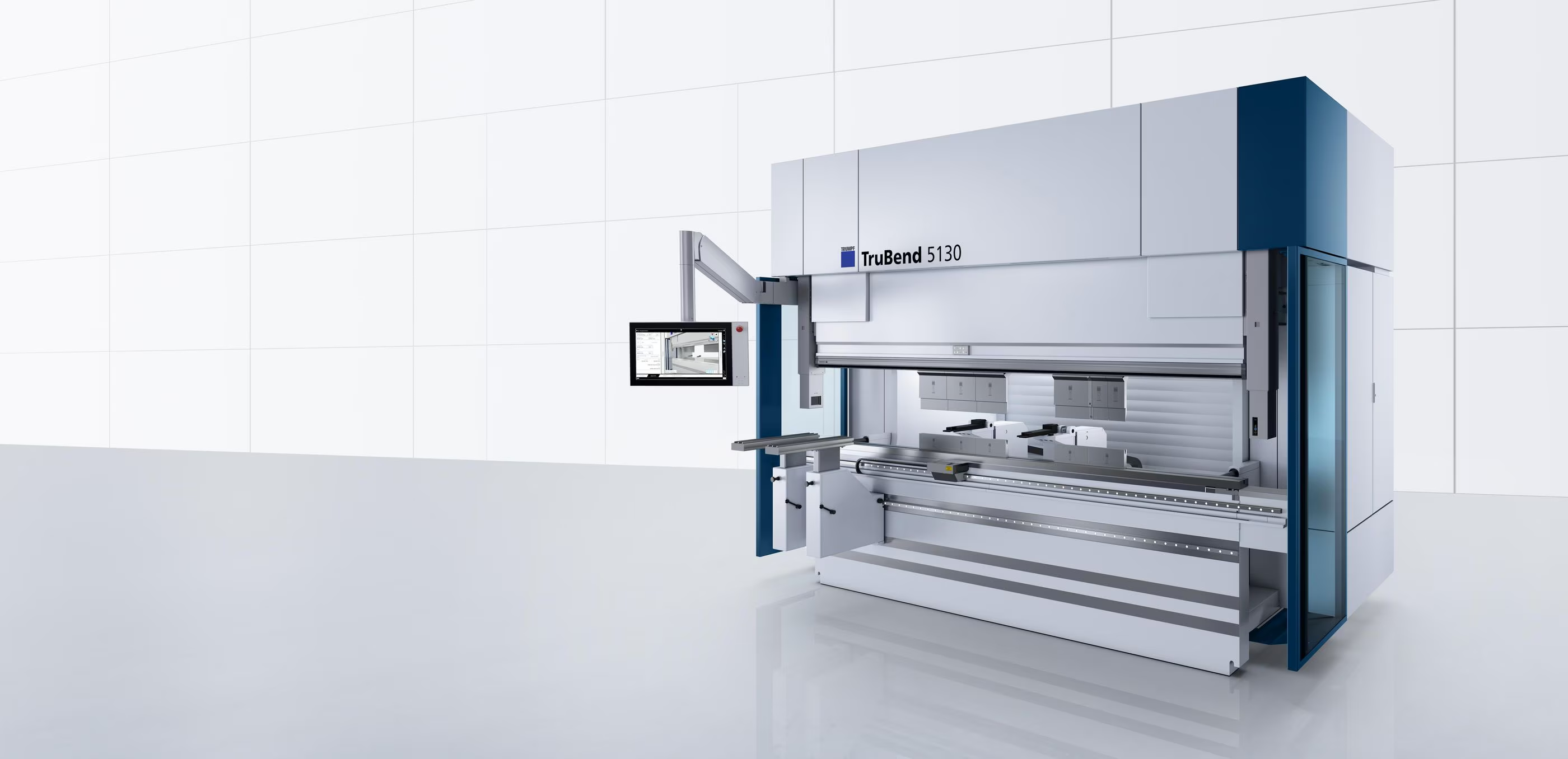
Understanding sheet metal fabrication starts with the language. This guide defines every critical term used in our bending and laser cutting processes — from how bend allowance is calculated to why your laser kerf width affects final part dimensions.
Whether you are preparing files for your first order or refining a complex multi-bend weldment, this reference will help you design parts that cut cleanly, bend accurately, and arrive exactly as specified.
Part 1 — Bending
- Bend Allowance & Deduction
- K-Factor by material
- Inner Radius selection
- Flange support rules
- Neutral Axis & Outside Setback
Part 2 — Laser Cutting
- Laser types & Kerf width
- Heat-Affected Zone (HAZ)
- Assist gas selection
- Minimum hole sizes
- Nesting & sheet sizes
Bend Allowance
The bend allowance is the length of material that undergoes deformation during the bending process. When a piece of metal is bent, the material around the bend stretches and compresses, affecting the final dimensions of the part.
Accurately calculating the bend allowance is essential for determining the correct size of the flat sheet metal before bending so that the finished product meets the desired specifications.
Bend Allowance Formula
// BA = Bend Allowance | π ≈ 3.14159
Bend Angle
The bend angle is the measure of how much the metal is bent, defined by the angle between the two flanges (sides) of the bent part. This angle dictates the shape and functionality of the final piece.
| Angle Range | Classification | Effect on Part |
|---|---|---|
| Less than 90° | Acute ("More Closed") | Sharper, tighter bends; requires higher tonnage |
| Exactly 90° | Right Angle | Standard bracket geometry; most common |
| 90° – 180° | Obtuse ("More Open") | Gentler bends; less springback compensation needed |
Understanding and specifying the correct bend angle is crucial for ensuring that the part fits correctly in its intended application.
Bend Deduction
Bend deduction is the amount subtracted from the total length of the flat sheet to achieve the desired dimensions after bending. It represents the difference between the sum of the outer dimensions of the finished part and the original flat length before bending.
Calculating the bend deduction allows engineers and fabricators to determine the precise size of the flat metal needed.
6 in + 6 in − 0.5 in = 11.5 inches flat blank length
// BD = Bend Deduction | OSSB = Outside Setback
Bend Line
The bend line is the exact location on the flat sheet where the bending operation will occur. It indicates where the punch or bending tool will make contact with the metal to form the bend.
In technical drawings and fabrication plans, the bend line guides the operator in positioning the metal accurately within the bending machine. Precise placement of the bend line ensures that the bends are made in the correct locations, which is essential for the part to meet design specifications.

Inner Radius
The inner radius is the radius of the inside curve of the bend. While bends in sheet metal are not perfectly circular due to material properties and the bending process, the inner radius serves as a critical design parameter.
It influences the bend allowance calculation and affects the material's flow during bending. A larger inner radius can reduce the risk of cracking or damaging the material, especially in thicker or harder metals.
| Material | Recommended Min. Inside Radius | Notes |
|---|---|---|
| Mild / Carbon Steel | 1× material thickness | Sharp bends possible on thin gauge |
| Stainless Steel | 1.5× material thickness | Work-hardens rapidly; avoid sharp bends |
| Aluminum 5052-H32 | 1× material thickness | Ductile; handles tight radii well |
| Aluminum 6061-T6 | 3× material thickness | Very prone to cracking at sharp bends |
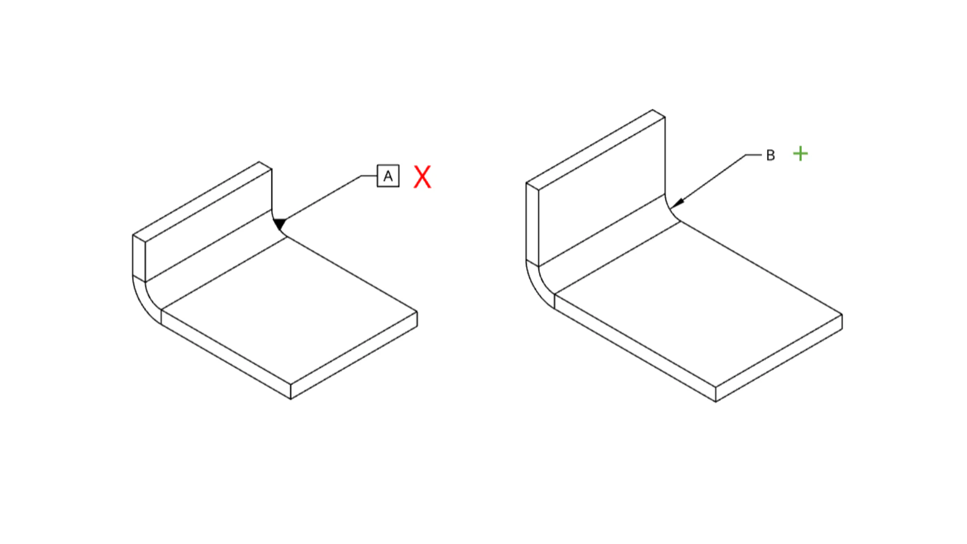
Minimum Bend Radius — What Happens When It's Too Tight
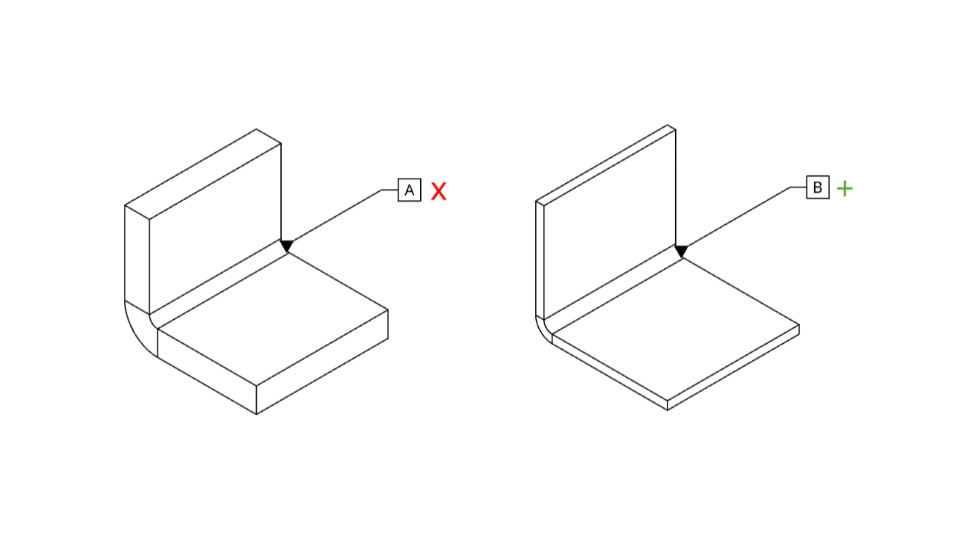
The diagram above shows what happens when the inner bend radius is specified smaller than the material thickness can support. Part A (❌ Incorrect): The inside corner of the bend is forced into a near-zero radius. The material cannot flow smoothly around the tooling — instead it buckles, cracks along the outer surface, and may delaminate at the grain boundary. The flange stands nearly vertical with a harsh, angular transition at the bend zone, which is a sign of overstressed material. This part would likely crack in service or fail a quality inspection.
Part B (✅ Correct): The inside corner has a properly sized radius — at least equal to the material thickness (1T). The material flows uniformly through the bend zone. The outside surface stays smooth and crack-free, and the flange sits at the intended angle with no evidence of stress damage. This is the geometry you should always aim for in your CAD model.
Why Does This Happen?
During bending, the outer surface of the material is in tension — it is being stretched. If the bend radius is too tight, that tensile strain exceeds the material's elongation limit before fracture. The result is visible cracking on the outside of the bend, or micro-cracking that creates a hidden stress riser that fails in service. Harder materials (6061-T6 aluminum, stainless steel) are far more susceptible to this than softer materials (5052-H32 aluminum, mild steel).
K-Factor
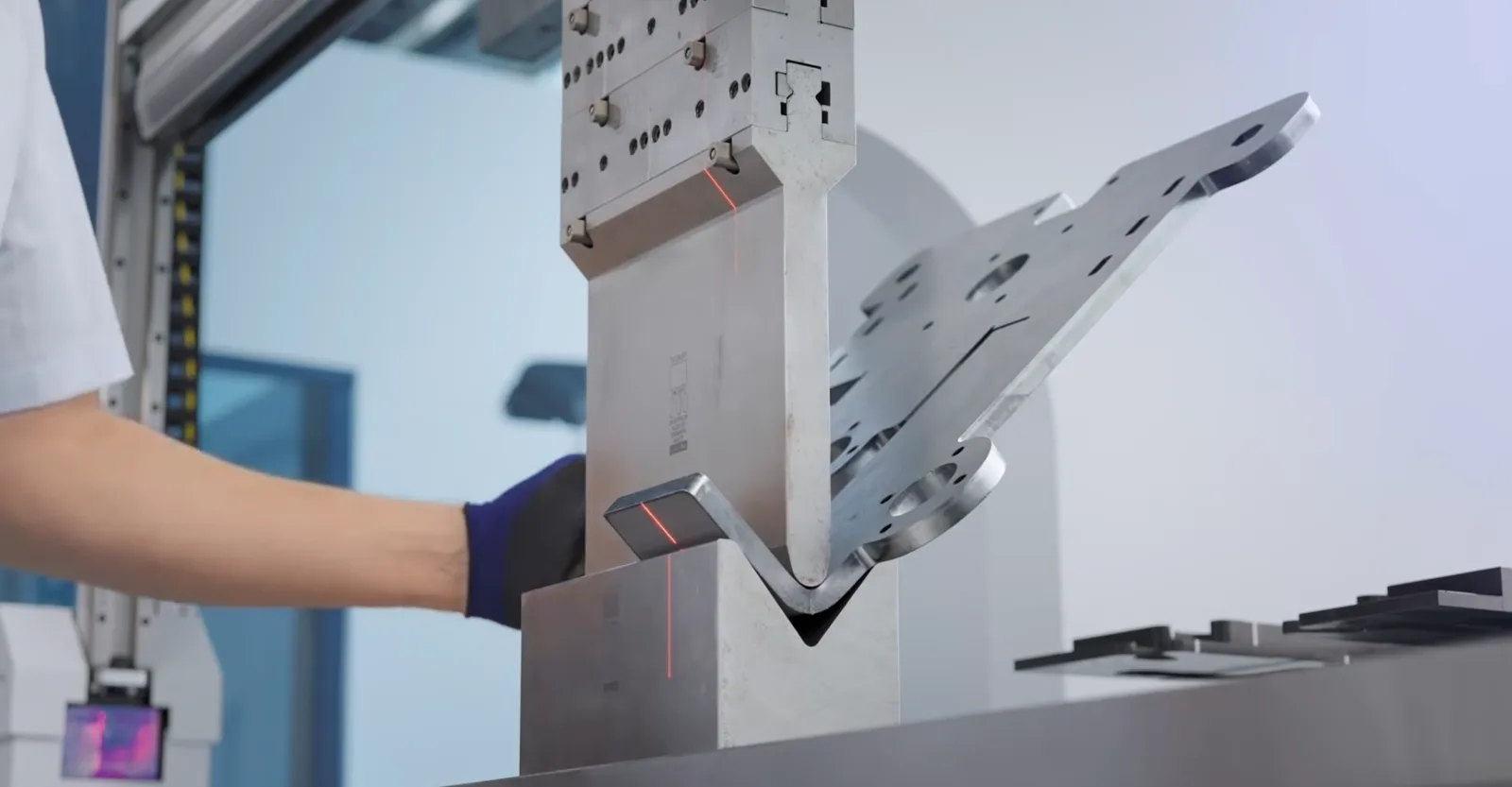
The K-factor is a ratio that describes the location of the neutral axis relative to the material's thickness during bending. The neutral axis is the theoretical line within the material that experiences no compression or tension.
The K-factor is calculated by dividing the distance from the inner surface of the bend to the neutral axis by the total thickness of the material. This coefficient is crucial for accurately calculating the bend allowance and bend deduction.
// t = distance from inner surface to neutral axis
// T = total material thickness
| Material | Typical K-Factor | Why |
|---|---|---|
| Aluminum | ~0.40 | Softer; neutral axis shifts toward inside due to more outward stretching |
| Mild Steel | 0.42 – 0.44 | Standard; moderate stretch/compression ratio |
| Stainless Steel | ~0.45 | Harder; neutral axis position shifts slightly due to material properties |
Minimum Flange Support
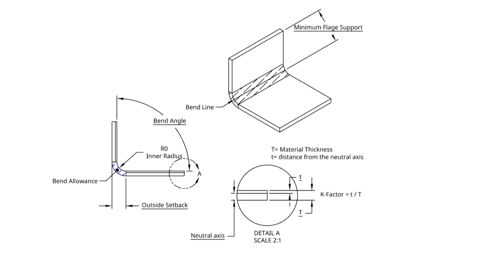
The technical diagram above is the single most important reference drawing for sheet metal bending — it labels every critical term in their correct geometric positions on an actual part. Study it carefully: the Bend Angle (θ) is measured between the two legs; the Inner Radius (R0) is the curved inside corner; the Bend Allowance is the arc length of material that gets consumed by the bend; the Outside Setback is the distance the flange overhangs beyond where the bend starts; the Neutral Axis is the theoretical zero-stress line inside the material (shown in Detail A at 2:1 scale); the K-Factor = t / T where T is total thickness and t is the distance from the inner surface to the neutral axis; and Minimum Flange Support is the zone at the top of the vertical flange that must be kept clear of holes and cutouts.
Minimum flange support refers to the minimum required distance between the bend line and the edge of the material. This distance ensures that there is enough material to contact the press brake die during bending, providing the lateral stability necessary for an accurate, straight bend. If a hole or slot is placed inside this zone, the material will pivot toward the weaker area instead of bending cleanly at the intended line.
Larger bend radii require larger V-die openings, which in turn demand more flange support. As a general guideline, minimum flange support equals the inner radius plus two times the material thickness — but always verify against the specific tooling your part will run on.
Minimum Flange Length
The diagram above directly compares two flanges on an L-bracket and illustrates what happens when the flange length is too short. Part A (❌ Incorrect): The flange is too short to seat properly in the press brake die. Instead of being held flat against the die surface, the flange curls upward and outward. The bend zone receives uneven support — one side of the punch contacts material, the other side hangs in open air. This causes the bend angle to be inconsistent along its length, producing a twisted or cammed part that cannot pass angle inspection.
Part B (✅ Correct): The flange is long enough to lay flat on the die surfaces on both sides of the bend. The punch and die can clamp the material symmetrically, distributing tonnage evenly. The bend comes out straight, at the correct angle, and without distortion anywhere along its length.
Minimum Flange Length Rule
The minimum flange length (measured from the outside of the bend to the edge of the material) must be long enough to clear the V-die opening and still provide flat support. A widely used rule of thumb:
// For most V-die tooling with standard opening ratios
// Larger bend radii or soft materials may require longer flanges
Hole Distortion During Bending
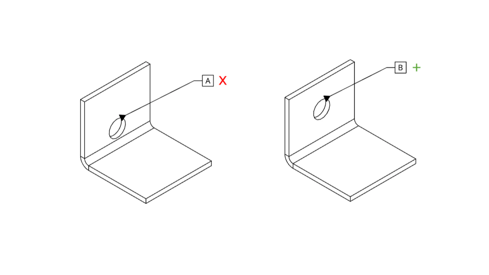
The diagram above shows one of the most common and costly sheet metal design mistakes: placing a hole too close to a bend. Part A (❌ Incorrect): A circular hole has been laser-cut close to the bend line, inside the bend allowance zone. When the part is pressed in the brake, the material around the bend stretches and compresses violently. Because the hole removes material from that zone, the surrounding metal has nowhere to distribute its strain — it flows into the hole opening instead. The result is a clearly oval, distorted hole that is no longer round, no longer in the correct location, and no longer the correct size. A fastener will not seat properly in this hole, and the part may be scrapped entirely.
Part B (✅ Correct): The same hole has been repositioned farther up the flange, well outside the bend allowance zone. The material around the bend can stretch and compress freely without the hole interfering. After bending, the hole remains perfectly circular, correctly positioned, and correctly sized — ready for fastener assembly without any rework.
Minimum Hole-to-Bend Distance
The safe minimum distance from the edge of a hole (or slot) to the start of the bend line depends on both the material thickness and the bend radius. Use this rule as a starting point:
// Measure from edge of hole to center of bend line
// Increase to 3× thickness for harder alloys (SS, 6061)
Sharp Interior Corners from Laser Cutting
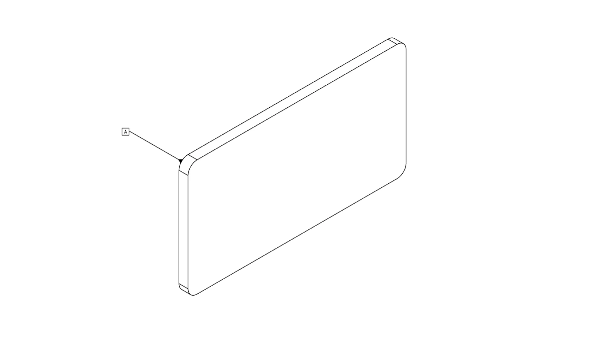
The diagram above compares two flat laser-cut parts with an interior re-entrant corner — the type of inside corner created when you cut a slot, notch, or tab into a sheet metal blank. Part A (❌ Incorrect): The interior corner is a perfect 90° sharp angle with no radius. At first glance this looks like good precision, but it creates two serious engineering problems. First, a stress concentration factor that is extremely high — sharp re-entrant corners under load or cyclic stress will initiate fatigue cracks. Second, the laser physically cannot produce a mathematically perfect zero-radius inside corner: it will always leave a small burned radius equal to approximately half the beam diameter. Specifying zero radius creates ambiguity in the drawing and the laser will always deviate from it.
Part B (✅ Correct): A deliberate small radius has been specified at the inside corner. This "corner relief" radius distributes stress over a curved surface rather than concentrating it at a point. The radius is intentionally designed, the laser hits its target geometry cleanly, and the part is significantly stronger in service. If this corner will be used as a bend relief (where two bend lines meet), the radius also prevents tearing during the press brake operation.
Recommended Inside Corner Radii
- For laser-cut flat parts only: Minimum 0.020″ (0.5 mm) radius at all interior corners.
- For bend relief cutouts: Minimum radius = material thickness (1T) at the intersection of two bend lines.
- For structural or fatigue-critical parts: Use the largest radius your assembly geometry allows — a larger radius always means a stronger part.
Neutral Axis
The neutral axis is an imaginary line within the material being bent where the fibers neither compress nor stretch — they remain neutral. During bending, the material on the inside of the bend compresses, while the material on the outside stretches.
The neutral axis shifts toward the inside of the bend based on the material properties and thickness. Understanding the position of the neutral axis is essential for calculating accurate bend allowances and for predicting how the material will behave during bending. It helps in minimizing errors and ensuring that the final part dimensions are as intended.
Outside Setback
Outside setback is the distance from the beginning of the bend allowance area to the outer surface of the flange on the finished part. It accounts for the material that "wraps around" the bend and is essential for determining the correct flat pattern dimensions.
The outside setback is used in combination with the bend allowance to calculate where to start and end the bend in the flat layout. Accurately calculating the outside setback ensures that after bending, the part's outer dimensions align with the design requirements.
// OSSB = Outside Setback
CNC Laser Cutting
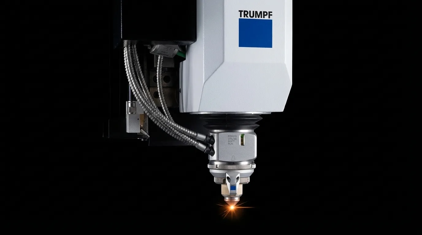
CNC (Computer Numerical Control) Laser Cutting is a precise manufacturing process that employs a high-powered laser beam directed by computer-controlled machinery to cut or engrave materials into specific designs and shapes. The laser beam melts, burns, or vaporizes the material, resulting in a clean and accurate cut edge.
This technology is widely used across industries including aerospace, automotive, electronics, and metal fabrication, due to its ability to produce complex shapes with high precision and repeatability.
Laser Types
Not all lasers are created equal. Different laser technologies are suited for different materials and applications.
- CO₂ Lasers: Utilize a gas mixture (primarily carbon dioxide) to produce the laser beam. Ideal for cutting non-metal materials like wood, acrylic, and plastics, and also capable of cutting some metals with appropriate power levels.
- Fiber Lasers: Use optical fibers doped with rare-earth elements to generate the laser. Highly efficient and suitable for cutting metals, offering faster cutting speeds and lower maintenance compared to CO₂ lasers. This is the laser type we use at Xeon NC.
- Nd Lasers: Solid-state lasers that provide high-intensity beams for applications requiring deep penetration, such as cutting thicker metals or for precision engraving.
Kerf
Kerf refers to the width of the material that is removed during the cutting process. In laser cutting, the kerf is typically very narrow, ranging from 0.1 mm to 0.5 mm, depending on the material and laser settings.
Understanding the kerf is crucial for designing parts that require precise fits, as it affects the final dimensions of the cut pieces. Our CAM software applies automatic kerf compensation to ensure your part dimensions match the CAD geometry exactly.
| Material | Typical Kerf Width | Notes |
|---|---|---|
| Thin gauge steel / aluminum (< 0.125″) | 0.1 – 0.2 mm | Very narrow; high detail possible |
| Mid gauge (0.125″ – 0.25″) | 0.2 – 0.35 mm | Standard production range |
| Thick plate (> 0.25″) | 0.35 – 0.5 mm | Wider kerf; allow for compensation in tight-fit designs |
Heat-Affected Zone (HAZ)
The Heat-Affected Zone is the area of the material that experiences thermal alteration due to the laser's heat during cutting. This zone may exhibit changes in microstructure, hardness, or mechanical properties, which can affect the performance of the final part.
Minimizing the HAZ is important to preserve material integrity, which can be achieved by optimizing laser parameters like power, speed, and focus.
Assist Gas
Assist gas is used in laser cutting to aid the cutting process and improve cut quality. The choice of assist gas affects cutting speed, edge quality, and the amount of dross (residual material) produced.
- Oxygen Enhances cutting of mild steel via exothermic reaction, increasing cutting speed — but may cause oxidized (burnt-orange) edges.
- Nitrogen Prevents oxidation, producing clean, oxide-free edges. Especially important for stainless steel and aluminum.
- Compressed Air A cost-effective option for cutting thin materials where edge quality is less critical.
Piercing
Piercing is the initial step where the laser creates a hole in the material before starting the cut path. Effective piercing is crucial for thicker materials and directly impacts edge quality at the start of every cut.
- Piercing Time: Needs to be controlled to prevent excessive melting or spatter. Too long a pierce on thin material burns the surrounding area.
- High-Speed Piercing: Uses a rapid pulse to break through the material quickly, reducing thermal input.
- Pulse Piercing: A lower-energy pulsing approach that limits spatter on thick plate, preserving pierce quality and reducing dross around the entry point.
Cutting Speed
Cutting speed is the rate at which the laser head moves across the material. It is a critical parameter that influences cut quality and production efficiency.
- Too Fast: Can result in incomplete cuts or rough, striated edges.
- Too Slow: Can cause excessive melting, wider kerf, and increased HAZ.
- Optimized Speed: Balances laser power and material properties to achieve desired results.
Effect of Material Thickness on Speed
- Thin Materials: Allow for higher cutting speeds and require less laser power.
- Thick Materials: Require higher laser power and slower cutting speeds to ensure full penetration.
Each laser machine has a maximum effective cutting thickness, depending on its power and the material type.
Dross and Slag
Dross (also known as slag) is the residue or roughness left on the underside of the material after cutting. It is caused by incomplete ejection of molten material due to incorrect cutting parameters.
- Causes: Incorrect cutting speed, assist gas pressure, or laser power settings for the given material and thickness.
- Prevention: Adjusting assist gas pressure, cutting speed, and laser power can minimize dross formation.
- Post-Processing: Dross may require secondary operations like grinding or sanding to achieve desired edge quality if parameters are not optimized.
Nesting
XeonNC2.webp)
Nesting is the arrangement of multiple parts on a material sheet to maximize material utilization. Efficient nesting directly lowers per-part material cost and reduces cutting time.
- Manual Nesting: Operator arranges parts — may not be optimal.
- Automatic Nesting Software: Uses algorithms to optimize part placement, reducing waste and cutting time. This is our standard workflow at Xeon NC.
Lead-In and Lead-Out
Lead-in and lead-out are small paths that the laser follows before and after cutting the main geometry. They are critical for edge quality at the start and end of every contour.
- Purpose: Prevents defects (burn marks, divots) at the start and end points of cuts by moving the pierce point and laser stop away from the finished edge.
- Placement: Should be positioned in non-critical areas of the part — typically a small relief tab area or an inconspicuous edge.
- Types: Straight or arc-shaped paths, depending on the material and cut quality requirements. Arc leads are preferred for thicker material.
Tabbing and Micro-Joints
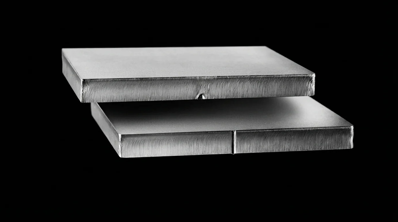
Tabs or micro-joints are intentional small connections left between the part and the surrounding material (skeleton) during cutting.
- Function: Prevents parts from tipping or shifting during cutting, which can cause the part to catch the laser head or affect cut quality.
- Size: Small enough to be easily broken or removed post-cutting — typically 0.5 mm – 2 mm wide depending on part weight and material.
- Application: Especially useful for small parts or intricate designs where movement during cutting would affect quality.
Including tabs in designs helps maintain part integrity throughout the cutting process. At Xeon NC, our TRUMPF Nano-Joint technology creates micro-tabs as small as 0.5 mm, allowing even very small parts to be held securely while remaining easy to separate after cutting.
Minimum Laser Cut Hole Diameter
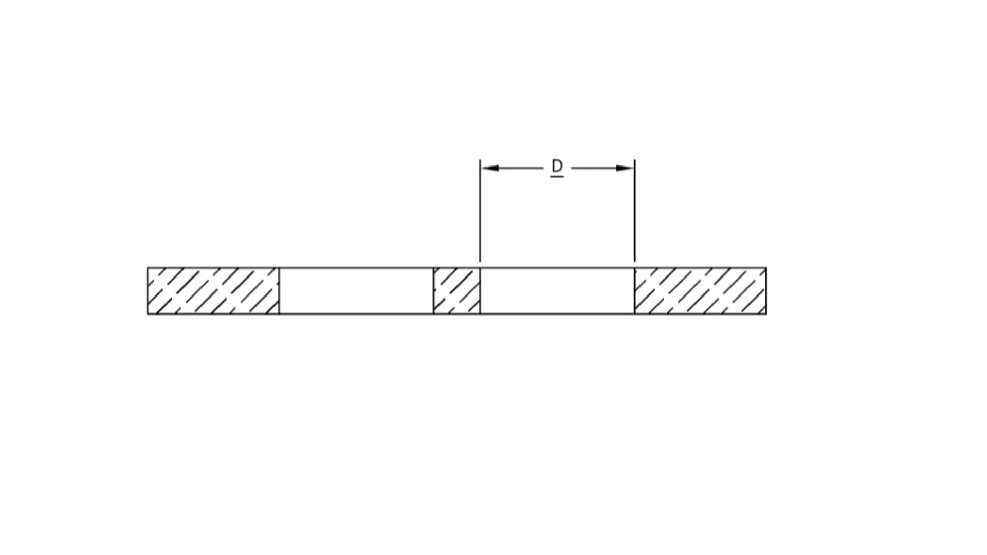
The diagram above shows a cross-section of a flat sheet with a hole cut through it. The hatched (cross-hatched) regions at the left and right represent the minimum wall of material that must remain on each side of the hole. The dimension D is the minimum acceptable diameter of the laser-cut hole. This minimum is not arbitrary — it is governed by two physical realities of the laser cutting process.
First, the laser has a finite beam/kerf width. If the hole diameter is smaller than the kerf, the laser cannot complete a closed contour — the cut path overlaps itself and the center slug never drops out cleanly. Second, thermal accumulation. When cutting a tight circular contour in thick material, the laser must slow down significantly on the curved path. In a very small hole, the laser essentially dwells in one spot too long, superheating the surrounding area. This causes the hole to burn oversize, the edges to become rough and re-hardened, and the surrounding material to warp.
The 1:1 Rule
As a universal rule of thumb, the minimum hole diameter should equal the material thickness — a 1:1 ratio. If your sheet is 0.125" thick, your smallest hole should be no smaller than 0.125" in diameter. For cleaner edges with no witness marks, design for 1.5× thickness when possible.
| Material Thickness | Min. Hole Diameter | Recommendation |
|---|---|---|
| 0.030″ – 0.060″ | ≥ 0.030″ | Clean cut; small pierce mark possible |
| 0.060″ – 0.125″ | ≥ 1× thickness | Ideal 1.5× for cleanest edges |
| 0.125″ – 0.250″ | ≥ 1× thickness | Pierce strategy changes; witness mark likely at minimum |
| 0.250″ – 0.500″ | ≥ 1.5× thickness | Wider kerf; significant thermal accumulation below 1.5T |
Scaling Features
If your design includes intricate patterns or small holes, consider scaling up the entire design or adjusting the size of those features to meet minimum size requirements. For features smaller than the laser can handle, post-process machining or drilling may be necessary.
Minimum Hole Distance Guidelines
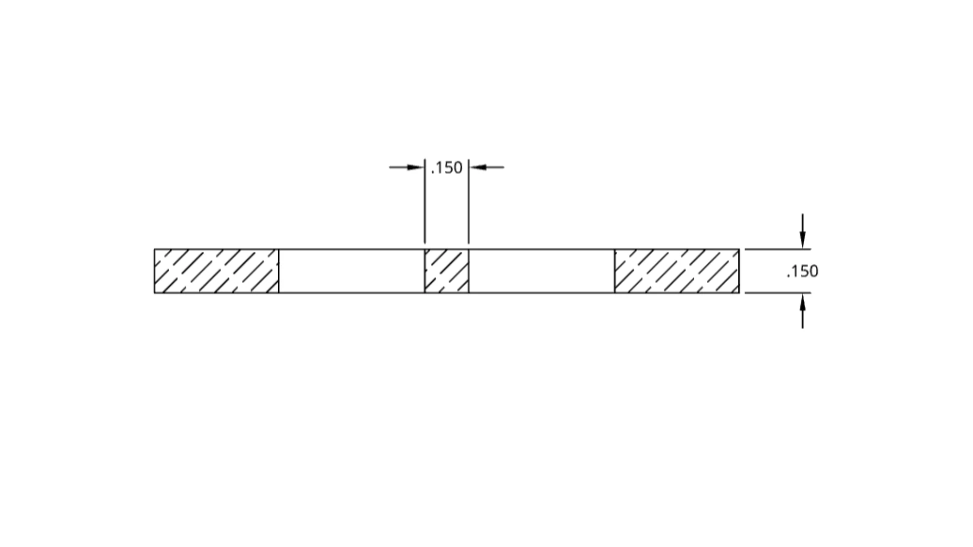
The diagram above shows two important minimum distance rules applied to a flat sheet cross-section. The hatched zones at the left edge, center (between holes), and right edge represent where material becomes structurally compromised if holes are positioned too close. Two critical dimensions are called out:
- Hole-to-Edge Distance (0.150"): The distance from the center of a hole to the nearest edge of the part must be at least 0.150" (or 2× material thickness if that is larger). If a hole is placed too close to the edge, cutting it laser effectively removes so much material from that zone that the edge becomes a fragile sliver. Under any handling, bending, or assembly force, that sliver will snap off — deforming the hole and ruining the part.
- Hole-to-Hole Distance (0.150"): The web of material between two adjacent holes must also be at least 0.150" (or 2× material thickness). When two holes are cut too close together, the thin web between them heats up excessively during the second cut — it can warp, melt partially, or simply lack the rigidity to hold its shape in the nesting fixture. The result is distorted adjacent holes and dimensional errors that accumulate across a hole pattern.
Min. Hole-to-Hole = max(0.150", 2 × Material Thickness)
// Measured from hole edge (not center) to part edge or adjacent hole edge
Nesting Parts on Standard Sheet Sizes
Efficient material utilization is achieved by nesting parts on standard sheet sizes. Designing your parts with these sheet dimensions in mind can significantly reduce material waste and cost.
Common Standard Sheet Sizes
| Imperial Size | Metric Equivalent | Typical Use |
|---|---|---|
| 72″ × 144″ | 1829 × 3658 mm | Large structural parts, max sheet size |
| 72″ × 120″ | 1829 × 3048 mm | Standard large format production |
| 60″ × 120″ | 1524 × 3048 mm | Most common production sheet size |
| 48″ × 120″ | 1219 × 3048 mm | Standard 4×10 sheet — widely stocked |
| 36″ × 120″ | 914 × 3048 mm | Narrow strip for smaller batch parts |