01 / DXF
Flat 2D partsOur choice for flat sheet-metal profiles cut by laser, waterjet, plasma, or router.
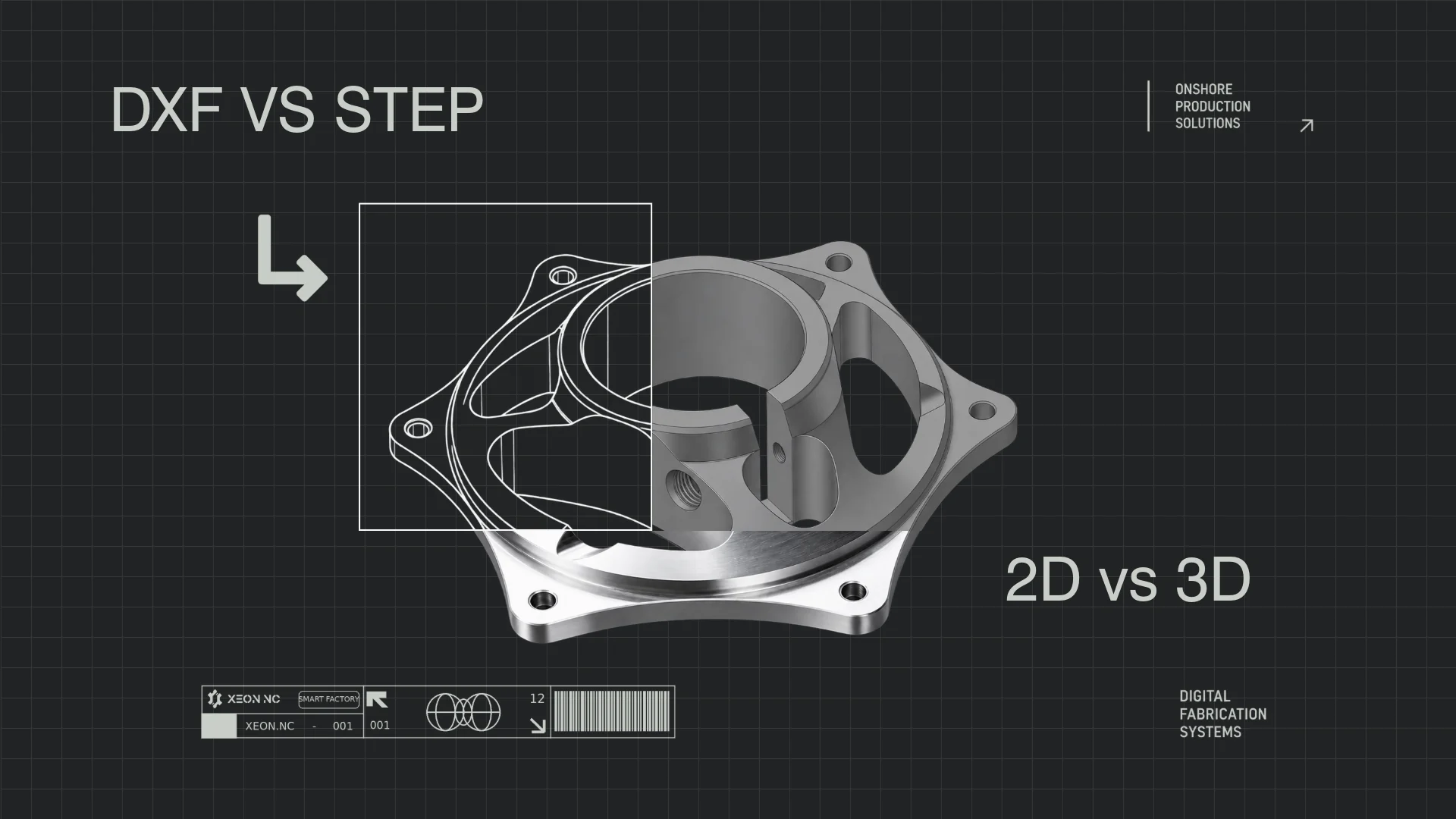
DXF is best for flat 2D sheet parts. STEP carries precise geometry for sheet metal—especially parts with bends—and CNC machining. STL is a mesh built for 3D printing.
Our choice for flat sheet-metal profiles cut by laser, waterjet, plasma, or router.
Our choice for sheet-metal parts, especially those with bends, CNC-machined parts, and precise 3D geometry.
Our choice for 3D printing, where a triangle mesh describes the printable surface.
Use 2D profiles for flat cutting, solid models for forming and machining, and meshes for printing.
It is the first input into a manufacturing system.
For decades, fabrication operated around drawings. A designer created a part. A drawing was generated. Someone at the fabrication shop interpreted that drawing, rebuilt manufacturing information from it, programmed the machine, and attempted to preserve the designer's intent through every translation.
That workflow works. But every translation introduces another opportunity for ambiguity.
Modern manufacturing is moving in a different direction: send more of the product definition downstream in a machine-readable form, and reconstruct less of it manually.
That is the fundamental difference between sending a DXF, STEP, or STL file. All three have a place, but they do not contain the same kind of geometry. The right choice depends on whether the part will be cut flat, formed or machined as a precise solid, or produced from a printable mesh.
At Xeon NC, each format has a clear manufacturing role.
A clean two-dimensional cutting profile. We use DXF for flat sheet-metal parts and similar laser, waterjet, plasma, or router work with no bends.
Best for flat cuttingA neutral product model with faces, holes, radii, bends, and topology. We use STEP for sheet-metal parts—especially those with bends—CNC machining, and other work whose finished 3D geometry matters.
Best for forming & machiningA triangle mesh that approximates the outside surface of a model. We use STL for 3D printing and print preparation, where slicer software needs a closed printable mesh.
Best for 3D printingDXF—Drawing Exchange Format—was introduced by Autodesk as a way of exchanging drawing information between systems. Autodesk's documentation describes DXF as a geometry format capable of representing entities such as lines, surfaces, polygons, blocks, and other drawing objects.
That makes DXF exceptionally useful for one thing: communicating geometry.
In sheet-metal fabrication, that commonly means a 2D profile: cut this outside contour, cut these holes, preserve these dimensions, and produce this flat part. For a flat laser-cut component, that can be exactly what is required.
But the manufacturing system still needs context. What material is it? What thickness? Is a line a cut, an etch, or construction geometry? Is the part already unfolded? Does the final component contain bends? Which direction do those bends go? What is the finished 3D geometry supposed to look like?
A conventional 2D DXF does not necessarily answer those questions simply by containing the profile. It gives the fabricator geometry and leaves other parts of the manufacturing definition to another source or to human interpretation.
STEP was designed around a different problem. STEP is part of the ISO 10303 family of standards for exchanging product data between different computer systems across the product lifecycle, including design and manufacturing.
NIST describes STEP files as being used to represent parts, assemblies, and Product and Manufacturing Information for interoperability between CAD, CAM, analysis, manufacturing, and inspection systems.
STL solves a third problem. Instead of preserving precise CAD faces and feature relationships, it approximates the model's outer surface with triangular facets. That makes STL simple and widely supported by 3D-printing slicers, but less suitable as the master file for sheet metal or CNC machining.
Consider a simple bent sheet-metal bracket: two holes, two flanges, and two bends.
Send the flat pattern as a DXF and the fabrication system can see the profile. But unless additional information is supplied, the system may not inherently know what that profile becomes after forming.
Send the finished solid as STEP and a capable manufacturing system can inspect the actual three-dimensional geometry.
This is a more important distinction than file extension. It is the difference between transmitting coordinates and transmitting context.
The manufacturing industry has been moving toward a connected model for years.
NIST calls the concept the digital thread: maintaining useful product information as it moves between design, manufacturing, inspection, and the rest of the product lifecycle.
NIST's research on smart manufacturing states that how design and manufacturing information is authored, exchanged, and processed is critical to competitiveness. It further argues that richer digital threads can reduce cycle time and improve the probability of producing correct parts the first time.
This is not primarily a CAD problem. It is an information architecture problem.
Every time information disappears from the digital model, someone downstream has to recreate it. Reconstruction can require:
Each individually appears small. At manufacturing scale, they compound.
Researchers at Purdue University describe Model-Based Definition, or MBD, as the use of digital product definitions to reduce the error-prone information exchanges associated with traditional drawing-based workflows while providing additional context through metadata.
A Purdue graduate research project examining model-based definition describes the broader transition from traditional 2D drawings toward 3D CAD models containing product information. The research identifies expected benefits including improved task efficiency, product quality, and reduced time-to-market, while also acknowledging that implementation practices vary.
NIST has reached a similar conclusion from the standards side. In 2024, NIST described STEP as a neutral format capable of carrying essential manufacturing and quality information in machine-readable form. NIST specifically connected this capability with automated CNC manufacturing and CMM inspection, citing reduced human error, increased efficiency, and lower operational costs as objectives of the model-based workflow.
For certain jobs, DXF is the cleaner input.
Consider a simple flat plate: no bends, no formed features, known material, known thickness, and one cutting operation. The manufacturer ultimately needs a 2D cutting profile.
In that case, a clean DXF can be extremely efficient. There is no meaningful advantage in reconstructing complex product information that does not exist. The geometry is effectively the manufacturing definition.
This is why DXF remains deeply embedded in laser cutting, plasma cutting, waterjet cutting, routing, and similar 2D manufacturing processes.
The equation changes when the part contains more information than a flat contour can communicate.
The finished 3D geometry lets software analyze faces, radii, edges, thickness, bends, flanges, and whether the design can unfold.
Pockets have depths. Holes have orientations. Faces have relationships. Curved surfaces live in three-dimensional space.
As geometry becomes more complex, the number and cost of assumptions needed to rebuild it from incomplete information grows.
This is the clearest example. A STEP model provides the manufacturer with the finished 3D geometry. Instead of receiving only the blank, manufacturing software can analyze the relationship between faces, radii, edges, and thickness. That gives automation more information from which to identify manufacturing features and validate the design.
A DXF may communicate certain profiles, but a CNC-machined component is fundamentally a 3D object. Pockets have depths. Holes have orientations. Faces have relationships. Curved surfaces exist in three-dimensional space. The 3D product model is therefore a much more appropriate representation of the component.
As geometry becomes more complex, information loss becomes more expensive. The number of assumptions required to reconstruct a component from incomplete information grows with the complexity of the component.
This is precisely the class of problem that STEP and model-based manufacturing standards were designed to address. ISO defines STEP around exchanging product information between systems throughout design, manufacture, use, maintenance, and other lifecycle stages.
STL is built around the needs of 3D printing, not precision CAD exchange.
An STL file represents a three-dimensional surface as a mesh of triangles. More, smaller triangles can approximate curved surfaces more smoothly, while fewer, larger triangles create a coarser result.
That mesh is useful for 3D printing because slicing and build-preparation software can turn the closed surface into printable layers. It is also why STL is not our preferred handoff for sheet metal or CNC machining: the mesh does not preserve the precise analytic faces, topology, bends, and manufacturing features available in a STEP solid.
Once a manufacturing platform understands a part as a 3D solid, software can inspect the geometry before production.
For sheet metal, that can include checks such as:
This changes quoting.
NIST's digital-thread work describes smart manufacturing in similar terms: well-structured 3D product models communicating design information into manufacturing and quality systems rather than repeatedly recreating that information between disconnected processes.
Imagine a chain:
At every step, a person interprets information generated by the previous person.
Now imagine:
Humans are still involved. Engineering judgment still matters. But they are no longer required to manually reconstruct every piece of information that the computer could have carried forward.
Automation is not simply making machines move faster. Automation is removing unnecessary interpretation between intent and execution.
Choose the format that carries the information your manufacturing process actually needs.
For some workflows, the best technical package is a STEP model as the authoritative geometry combined with a drawing or other documentation for requirements that are not reliably encoded in the model.
Dimensions with special tolerances, finishes, critical-to-function features, thread requirements, weld requirements, inspection requirements, and other manufacturing notes still need to be communicated clearly.
The goal is to stop asking highly skilled people to repeatedly reconstruct information that already existed upstream.
Purdue describes modern model-based definitions as a mechanism for more efficient automatic information exchange through the product lifecycle. NIST's work on STEP and the digital thread is built around the same premise: manufacturing improves when product information remains machine-readable as it moves between engineering systems.
That is the larger idea behind choosing between DXF, STEP, and STL. It is not really about file extensions. It is about matching the geometry representation to the manufacturing process and preserving the information production needs.
At Xeon NC, we prefer STEP for parts where the 3D model gives our manufacturing system useful information—particularly formed sheet metal and other geometry where understanding the final component matters.
DXF still has an important role for simple flat-cut components.
For 3D printing, STL provides the mesh needed for slicing and build preparation.
But the direction of modern manufacturing is clear. More geometry becomes structured data. More manufacturing constraints become computable. More quoting becomes automatic. More validation happens before material reaches a machine.
The factory receives a better representation of engineering intent, and the number of assumptions between design and production decreases.
That difference is the foundation of the digital factory.
Upload a DXF for flat 2D cutting, a STEP for bent sheet metal or CNC machining, or an STL for 3D printing. Add a drawing when tolerances, finishes, certifications, inspection, or other requirements control the part.
Upload Parts & Get a Quote