Picking Tooling for the Bend
A Xeon NC design guide for selecting the right punch and V-die from material, thickness, and target radius — the same air bending logic our 2D Bend Check applies before every press brake job.
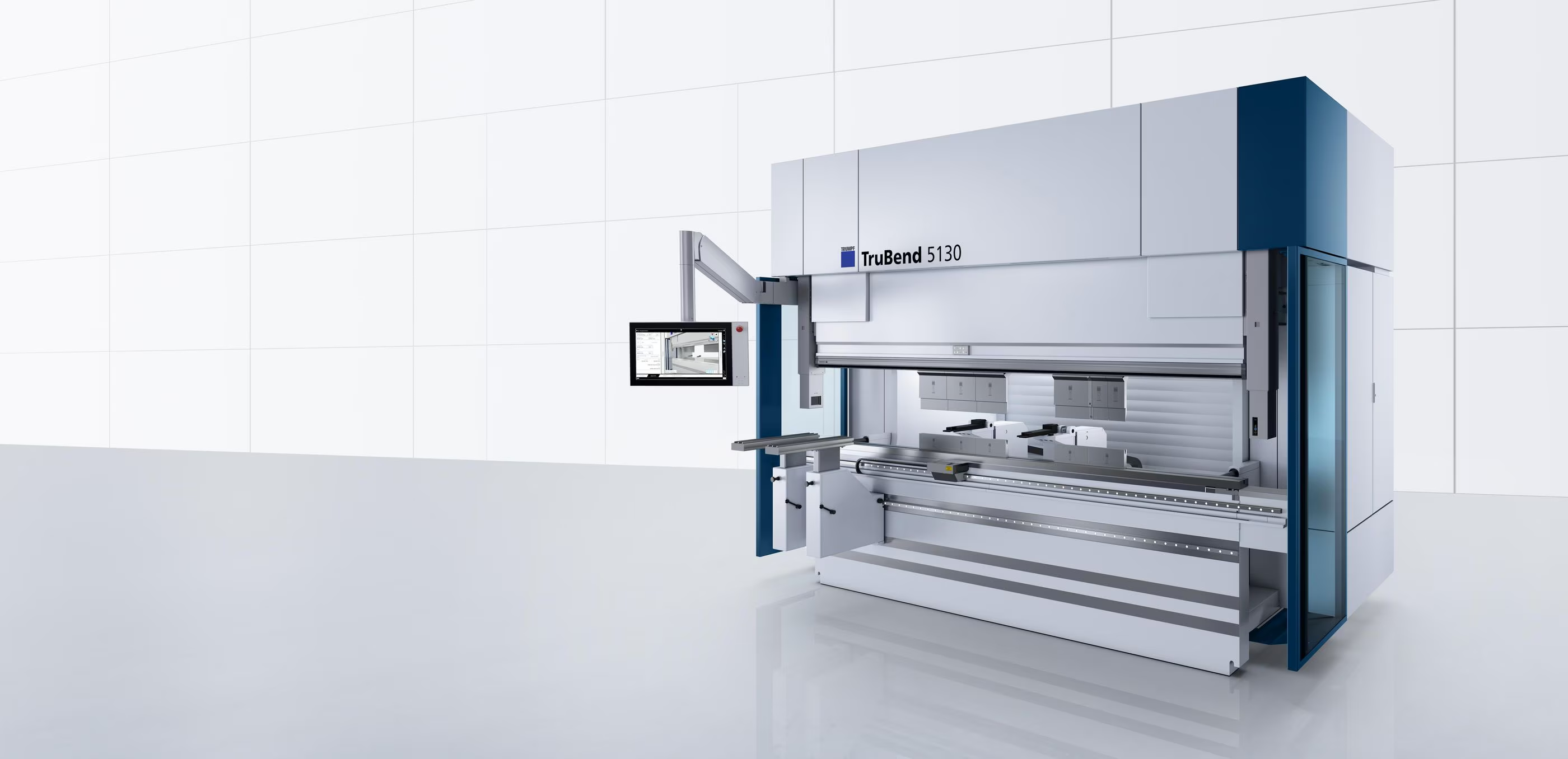
Tooling is not chosen by part — it is chosen by material. The combination of thickness, alloy, and target inside radius dictates the V-opening, the punch tip radius, and the available tonnage window. Get the tooling pairing wrong and every downstream consequence — radius, springback, flange minimum, tonnage overload — falls out of spec at once.
This guide walks through the math used by our 2D Bend Check: how it derives a recommended V-opening, why the inside radius forms at roughly 16% of the V, when to escalate to acute or gooseneck punches, and how to verify that the punch and die will not collide on the part you have drawn. The numbers come from standard air bending practice — the same rules Trumpf publishes for their TruBend machines using WILA OW/EV style tooling.
Air Bending Fundamentals
Modern CNC press brakes — including the Trumpf TruBend series we run — form parts almost exclusively through air bending. The punch descends into the V-die only deep enough to press the sheet to a target angle. It never bottoms out against the die wall. Three properties fall out of that single fact, and every tooling decision starts from them:
- The die never defines the radius. The inside bend radius is formed by how far the punch pushes the sheet down into the V — not by the radius machined into the die shoulder. A single V-die produces every radius from sharp to wide simply by changing penetration depth.
- The same tool runs every angle. One punch / die pair forms 30°, 90°, and 120° bends. The ram controller varies the Y-axis depth. This is the property that makes air bending so much cheaper than bottoming or coining — one tool stack runs an entire job folder.
- Springback is part of the program. Because the punch never seats the material against the die, the elastic component recovers when the punch retracts. The CNC simply over-bends by a few degrees to compensate. Springback magnitude depends on material strength, not on tooling — but tooling choice affects how predictable that springback is.
The V-Opening Rule
The first decision is V-die opening width. Trumpf and every major tooling vendor publish the same rule of thumb: V-opening should be a fixed multiple of material thickness. Too narrow and the die over-stresses the metal and crushes the bottom face; too wide and the bend opens up, the radius blows out, and the flange-length minimum becomes unrealistic.
These are exactly the factors the 2D Bend Check uses. The narrower factor for aluminum reflects its lower yield strength — it can form in a tight V without cracking. Stainless and high-strength alloys need the extra V-width to avoid outer-fiber cracking and to keep tonnage within machine limits.
Material Factors at a Glance
The full table the simulator uses — V-multiplier sets the die, radius-multiplier modifies the formed inside radius, and the load factor scales tonnage relative to mild steel:
| Material | V × Thickness | Radius Factor | Load Factor |
|---|---|---|---|
| Aluminum 5052-H32 | 6× | 0.80 | 0.55 |
| Mild steel (A36 / A1008) | 8× | 1.00 | 1.00 |
| Galvanized steel | 8× | 1.00 | 1.08 |
| Stainless steel 304 / 316 | 10× | 1.20 | 1.50 |
| High-strength steel | 12× | 1.60 | 1.85 |
Read across the row to dimension your tooling. A 0.090" stainless part needs a V near 0.90" (≈ 22 mm — call out a W20 or W25 die), will form to roughly a 0.17" inside radius on that die, and will draw 50% more tonnage than the same gauge in mild steel.
The 16% Radius Rule
The single most useful number in air bending: the inside bend radius forms at roughly 16% of the V-opening. This holds for mild steel and is the baseline every press brake operator works from. Aluminum lands tighter (12–14%), stainless lands wider (18–20%), and the material radius factor in the table above adjusts it.
This is the rule that lets you pick a die for a target radius rather than just for thickness. Need a 0.125" inside radius? On mild steel that calls for V ≈ 0.125 / 0.16 = 0.78" (a 20 mm V). On stainless, V ≈ 0.65" — a tighter die. On aluminum, V ≈ 0.98" — a wider one.
Choosing a Punch
The V-die sets the radius and the tonnage; the punch sets whether the geometry is reachable. Three properties matter: tip radius, included angle, and height (clearance). Tip radius needs to be equal to or smaller than the radius you want to form — never larger, or the punch acts like a radius punch and forces the part wider. Included angle has to be tighter than the bend angle you are forming, with margin for over-bend. Height has to clear adjacent flanges as the part rotates through the die.
Our standard punch library
| Punch | Tip Radius | Height | Use case |
|---|---|---|---|
| OW202/K R1 | 1.0 mm | 120 mm | Standard 88° punch — go-to for most flat parts in 16–10 gauge. |
| OW202/S R1 | 1.0 mm | 220 mm | Same tip, taller body — when adjacent flanges clear the ram only at 220 mm. |
| OW200/S R1 | 1.0 mm | 220 mm | Acute-angle 30° punch — required for any bend tighter than ~80°, including U-channels closed beyond 90°. |
| OW203/S R4 | 4.0 mm | 220 mm | Large-radius punch — use when the part calls for a soft inside radius and a small V would coin the inner fibers. |
| OW300/S R1 | 1.0 mm | 300 mm | Extra-tall standard punch for deep boxes — clears tall opposing flanges that would crash a 220 mm tool. |
| Gooseneck | 1.2 mm | ~66 mm body offset | Curved body reaches over a previously formed return flange. Reserve for box-and-pan work — gooseneck punches are weaker and tonnage-limited. |
Picking included angle
- 88° standard punch covers every bend from 90° up to the open 180° range. The 2° margin lets the CNC over-bend for springback without the punch tip kissing the die wall.
- 30° acute punch is required for any closed bend — anything under 90°. Specify acute the moment you draw a hem prep, an offset, or a closed U. The OW200/S is our standard acute.
- Large-radius punch (R4 or R5) replaces a standard punch when the target inside radius is wider than what the V can naturally produce. Pairing R4 with a small V is illegal — the punch radius would exceed the V's radius envelope and the material would bridge instead of forming. Always pair large-R punches with wide V-dies.
Tonnage & Load Limits
Once V is chosen, tonnage follows directly. The classic air bending formula — published by every press brake OEM, including Trumpf — is:
Every die carries a published tonnage limit per foot — the structural cap on what the die body itself can take before deforming. Exceeding it cracks the die. The simulator flags this as an over-tonnage warning whenever computed load passes the die's rating.
Minimum Flange Length
The V-die rests the sheet on its two shoulders. If a flange is shorter than the distance between the shoulders, it falls into the die — there is nothing for the sheet to bear against and the bend will not form correctly. The 2D Bend Check estimates the minimum from:
The 0.7 factor accounts for the sheet pivoting on the die shoulder rather than the full V centerline. Add the punch tip radius (so the punch has somewhere to land), add the material thickness (so the sheet does not just flap off the shoulder). The result is the absolute minimum — for production work, design at least 1.2× this number to keep bends repeatable.
The Selection Workflow
Pulling all of this together, the procedure for selecting tooling from scratch:
Using the 2D Bend Check
The Xeon 2D Bend Check automates every step above. Build the flat profile, set material and thickness, and the right panel will:
- Display the recommended V-opening alongside your selected die — with warnings when the die strays outside the 0.72×–1.55× window.
- Compute total tonnage at the brake and tons per foot, flagging over-tonnage against the loaded die's rating.
- Show the minimum flange length live as you adjust segments. Flanges shorter than the minimum highlight in the warning panel.
- Render the actual WILA punch and die DXF geometry — OW202, OW200, OW203, OW300, EV002, EV004, EV006, W30, W50 — against the part. Punch and die collisions surface visually before the job is released to the floor.
- Predict the formed inside radius using the V × 0.16 × radius-factor rule, so the drawing radius and the actual radius do not drift.
For routine sheet metal — 16 gauge mild steel, 0.060" aluminum, 14 gauge stainless — the defaults the Bend Check picks are the same defaults our programmers would pick by hand. Where it earns its keep is on the awkward parts: deep boxes that need a 300 mm punch, acute hems, soft-radius covers, and any time tonnage is anywhere near the brake's ceiling.