The Bend Affected Zone
A Xeon NC Process Guide on designing sheet metal parts around the deformation zone created during CNC press brake bending.
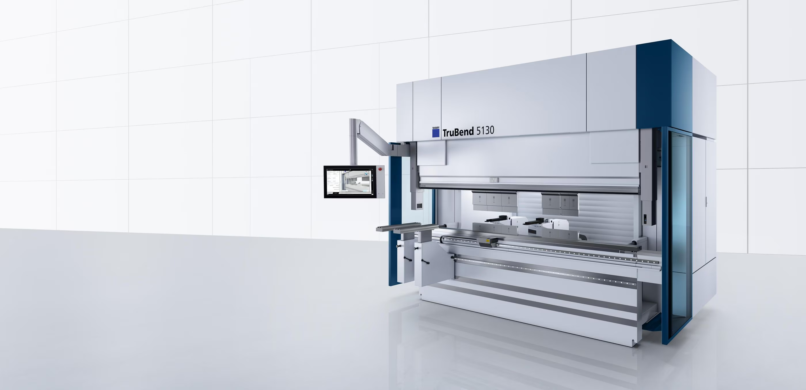
Every bend formed in sheet metal physically distorts the material surrounding the bend line. This region of permanent plastic deformation is called the Bend Affected Zone (BAZ), and it governs the placement of every hole, slot, notch, and edge feature on your part.
Unlike the Heat Affected Zone (HAZ) in laser cutting, the BAZ is entirely mechanical. No thermal energy enters the equation. Instead, the V-die and punch forcefully compress the outer fibers of the metal past yield into permanent plastic deformation, while the inner fibers simultaneously undergo extreme compression. The result is a corridor of structurally altered material flanking both sides of the bend centerline.
How the Bend Affected Zone Forms
When a press brake punch forces sheet metal into a V-die, the material undergoes two simultaneous mechanical events across the bend radius:
- Outer Fiber Tension: The material on the outside of the bend is physically stretched. Individual grain boundaries elongate in tension, thinning the cross section along the outer radius. In severe bends or brittle alloys, this tension can exceed the ultimate tensile strength and cause visible surface cracking.
- Inner Fiber Compression: The inside of the bend experiences the inverse — material is forcefully compressed together, thickening the cross-section slightly. In softer alloys this forms a smooth shoulder, but in harder grades it can buckle or create surface wrinkles.
- Neutral Axis Shift: The theoretical "zero-stress" plane between tension and compression does not remain at the geometric center. Under significant plastic deformation, it migrates inward toward the compression side — which is why bend allowance calculations require a K-factor rather than simply halving the thickness.
Hole & Feature Placement Rules
The most common design failure in bent sheet metal is placing holes, slots, or notches too close to a bend line. When a feature falls inside the BAZ, the press brake physically drags it along with the deformation field.
What Happens When Features Enter the BAZ
- Hole Distortion: A round hole becomes oval or teardrop-shaped as the material surrounding it stretches unevenly. Fasteners no longer seat correctly,' and press-fit tolerances are destroyed.
- Slot Warping: Rectangular slots located near a bend will ribbon and twist, losing their parallel sidewalls. Mating tabs from adjacent parts no longer engage cleanly.
- Edge Tearing: When a feature like a notch sits directly at the bend tangent, the outer-fiber tension can rip the metal starting from the notch edge. This is a catastrophic structural failure and will scrap the part.
How Different Materials React
The severity and spread of the BAZ is directly tied to the base material's ductility, grain structure, and temper condition:
Aluminum
- 5052-H32: The gold standard for sheet metal bending. This alloy's fine, uniform grain structure distributes deformation evenly. The BAZ remains narrow and predictable, allowing features like holes to be placed much closer to the bend line with minimal distortion risk.
- 6061-T6: Significantly less forgiving. The T6 temper produces a hard, brittle grain structure that resists plastic flow. The BAZ is wider and more aggressive — outer fiber cracking is common at tight radii. Minimum bend radii must be 1× to 2× material thickness or larger.
Carbon Steel
- A36 / A1008 (Mild Steel): Excellent ductility with a wide forming window. The BAZ is moderate, and standard 2× MT rules are reliably safe. Grain direction still matters — bending perpendicular to the rolling direction is always preferred.
- High-Carbon / Spring Steel: Extremely narrow forming window. The BAZ extends significantly wider and the risk of cracking is exponentially higher. Features must be kept well beyond the standard minimums.
Stainless Steel
- 304 Stainless: Good ductility but work-hardens aggressively during bending. The BAZ itself becomes demonstrably harder than the parent material. This is important for secondary operations — tapping or drilling into the BAZ of 304 stainless will encounter significantly increased tool wear.
- 316 Stainless: Very similar behavior to 304 but marginally more ductile, offering slightly tighter minimum bend radii.
Designing Sheet Metal Around the BAZ
Approaching your flat pattern layout with the BAZ in mind from the start eliminates costly redesigns and rejected parts:
1. Map the BAZ Before Placing Features
On your flat pattern, draw ghost lines at the minimum clearance distance on both sides of every bend line. These represent your "no-feature zones." No hole center, slot edge, or emboss boundary should cross into this corridor.
2. Use Bend Relief Cuts
When a bend does not span the full width of a part — meaning the bend line terminates mid-sheet — you must include bend relief cuts at both ends. These are small rectangular or radius-ended slots cut into the flat blank at the exact termination point of the bend. Without bend reliefs, the metal will tear or buckle unpredictably at the transition.
3. Shift Features to Safe Flanges
If a mounting hole or slot must exist near a bend, consider whether it can be relocated to the opposite flange entirely. Post-bend drilling is an option, but it adds secondary operations and cost. Pre-planning avoids this.
4. Specify Radius, Don't Default
Many designers leave the bend radius unspecified, assuming the shop will choose appropriately. This is risky. Always specify your inside bend radius on the drawing. A tighter radius creates a more severe BAZ; a larger radius softens it considerably. For critical parts, specify a radius equal to or greater than 1× material thickness as a baseline.
5. Account for Springback
After the punch retracts, the elastically strained outer fibers partially recover, causing the bend angle to "spring back" slightly. This is not BAZ distortion — it is elastic recovery. But understanding both phenomena together allows you to correctly predict final part geometry. Harder materials spring back more.
Springback also has a consequence the BAZ rules do not cover. Because the brake has to over-bend past your target angle to compensate for it, every feature on the moving flange swings past its final position while the part is still under load — roughly 0.017″ per inch of distance from the bend line, per degree of recovery. A feature that clears in the finished part can still be struck mid-stroke. Part-on-Part Collision covers how to size those clearances.
Common BAZ Design Failures
Understanding what goes wrong is just as valuable as knowing the rules:
- Oval Mounting Holes: A Ø0.190" clearance hole placed 0.150" from a bend line on 0.090" aluminum. The hole distorts into an oval during forming. The screw no longer aligns with the mating part. Fix: relocate the hole center to at least 0.270" from the bend line.
- Torn Notch Edge: A decorative notch is placed exactly at the bend tangent on 18-gauge mild steel. During bending, the outer fibers tear from the notch corner outward. Fix: add a relief radius at the notch corner or move the notch entirely out of the BAZ.
- Crushed Emboss: A dimpled or lance feature placed within the BAZ gets flattened or inverted when the V-die closes over it. Fix: Move embossed features at least 3× MT + R from the nearest bend line.
- Missing Bend Relief: A partial-width bend terminates at the edge of a tab. Without a relief slot, the metal tears at the transition between bent and unbent zones. Fix: always add relief cuts (minimum 1× MT wide, 1× MT + R deep) at bend terminations.