Part-on-Part Collision
A Xeon NC Design Guide on the interference that only exists mid-stroke — why springback forces the press brake to over-bend past your angle, how far that pushes a flange, and how much clearance a formed feature needs to survive it.
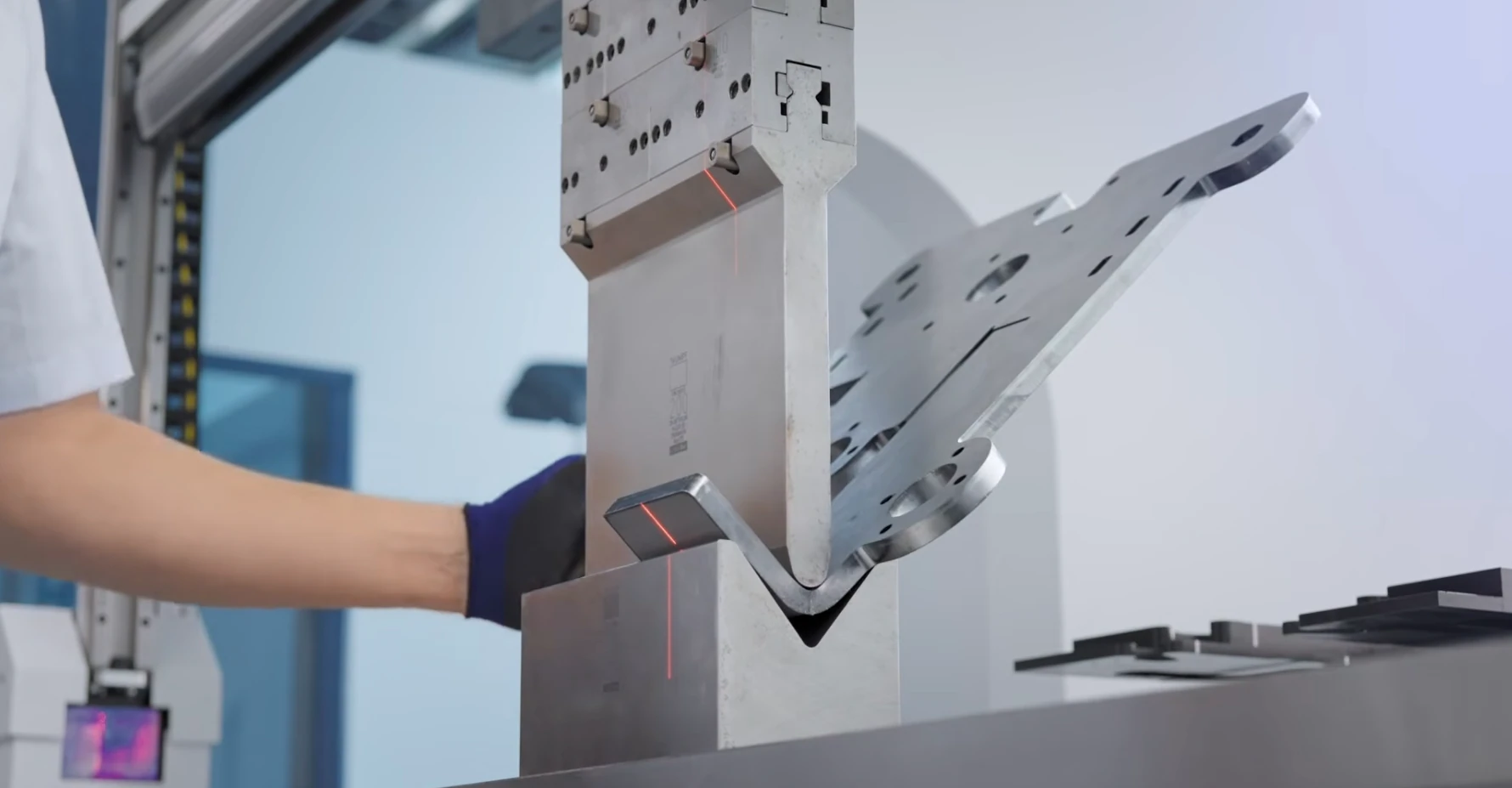
Mid-stroke, on the TruBend 5170. The flange in this photo is not at the angle the drawing calls for — it is past it, and it will stay past it until the ram lifts. Every clearance on a formed part has to be big enough for that moment, not just for the finished geometry.
A part-on-part collision is interference that does not exist in your CAD model. The finished part measures correct, the flat pattern is right, and every gap you dimensioned is still there when the part is in your hand. The collision happens in the two seconds while the part is being formed, between one face of your part and another face of the same part — and by the time it is over it has already put a witness mark, a dent or a kink in the metal.
The reason it does not show up in the model is that a press brake cannot bend to the angle you asked for. It has to bend past it, because the metal springs back the instant the pressure comes off. That over-bend is not optional and it is not small. At the bottom of the stroke your 90° flange is sitting at 87° or 88°, and everything attached to that flange is somewhere it will not be when the part is finished.
If something else on the part is standing in that somewhere, they meet. This guide is about predicting where.
Springback, and the Over-Bend That Answers It
When a punch drives sheet into a V-die, the material yields and takes a permanent set — that is the bend you keep. But it is also elastically strained, and elastic strain is recoverable. The moment pressure is released, the outer fibers relax and the flange rotates back open. That recovery is springback, and it is the reason a brake operator has never in the history of the trade bent a 90° part by stopping at 90°.
The compensation is over-bending: form past the target by the amount the part is going to recover, then let it spring back onto the number. Our TruBend 5170 does this measurement per stroke rather than from a table — the ACB laser reads the real angle while the sheet is still under load and computes the over-bend from the recovery it just measured on that specific piece of metal. That makes the finished angle reliable. It does not make the over-bend go away. The machine still has to physically push the flange past where you want it.
Notice which number is the useful one. Nobody designs to an angular tolerance on a bend they are not measuring, so 2° of recovery reads as trivia. The 0.105″ is the number that decides whether your part collides, and it is the number that never appears anywhere on a drawing.
How much recovery you actually get depends on the material and the tooling, not on the geometry of the collision:
| What drives it | Effect on the over-bend |
|---|---|
| Yield strength | Higher yield stores more elastic energy, so more of the bend is recoverable. 6061-T6 needs materially more over-bend than 5052-H32 at the same thickness on the same tooling. |
| Inside radius to thickness ratio | The dominant geometric term. A generous inside radius springs back much harder than a tight one, because a larger share of the section is in the elastic range. Wide V-openings therefore cost you clearance. |
| Work hardening | 304 stainless hardens as it forms, so the metal at the end of the stroke is stronger than the metal at the start. Recovery on stainless is both larger and less repeatable than on aluminum. |
| Actual thickness | Mill tolerance is real. A sheet at the thin end of the band bends and recovers differently than one at the thick end, out of the same lot. |
| Grain direction | A bend running with the rolling direction recovers differently than one running across it, on the same blank. |
The formula is worth having, but the point of putting the two equations next to each other is the second one. Springback is an angle, and angles are cheap. Collisions are linear, and the linear number is the angle multiplied by however far out the feature sits. You can pull the actual bend deduction, K-factor and inside radius we program for any material and gauge we stock from the Bending Ontology & Material Specs lookup.
Degrees Become Distance
This is the whole mechanism of a part-on-part collision, and it is a lever arm. Rotate a flange by a small angle and every point on that flange moves along an arc whose radius is its distance from the bend line. Close to the bend, nothing moves. Six inches out, a couple of degrees is a visible, measurable, part-wrecking amount of travel.
Read one number off it and keep it: one degree of recovery spends about 0.017″ of clearance for every inch of arm. That single figure lets you check a part in your head. A tab 5″ from the bend line, in a material you expect to recover 3°, is going to swing 5 × 3 × 0.017 ≈ 0.26″. If there is a quarter inch of air there, it is a collision.
Two consequences fall out of the shape of that chart, and both of them are design levers you actually control:
- Move the obstacle toward the bend line, not away from it. Everyone's instinct with a clearance problem is to add distance. Here distance is the multiplier. A notch relocated from 5″ out to 1.5″ out cuts its own travel by two thirds without changing a single clearance dimension.
- Specify a tighter inside radius where you can afford to. Recovery scales with the radius-to-thickness ratio, so tooling selection sets your over-bend before geometry ever enters the picture. See Picking Tooling for the Bend for how punch and V-opening decide the radius you actually get.
Where the Collision Actually Happens
Put those two ideas together on a real part and the failure mode is obvious in hindsight. Take a bracket: a web, a wall formed up off the end of it, and a lip returned back over the web from the top of that wall. Somewhere along the web there is a small tab, formed up early in the sequence, that the lip is supposed to pass over with a little air between them.
Watch it happen on a real part
The drawing above makes the argument in cross-section. This next one lets you check it on an actual CAD file — two of them, in fact. Both are the same 5″ × 3″ × 1.5″ pan in 0.100″ material, 0.050″ inside radius, four walls bent up at 90°: an ordinary tray, modelled correctly, that measures right in both versions. The only difference is at the corners. The first leaves a 0.010″ gap where the side walls butt into the ends; the second is relieved to the minimum a shop would ask for, which opens that gap to 0.050″. Press play, watch what the last two bends do to those corners on the way down, then switch parts and watch the identical stroke go through without touching.
This figure needs WebGL, which your browser has not made available. The cross-section above carries the same argument: at 2° of over-bend the wall top swings 0.047″ against a 0.010″ gap, so the corners are in contact for three quarters of the stroke. Open the gap to 0.050″ and the same stroke clears by 0.003″.
Here is what makes this failure so easy to ship: released, the part is fine. The lip springs back to 90°, the gap reopens to 0.040″, and the part measures exactly as drawn. Inspection passes it. The CAD model was never wrong. The interference existed only while the ram was down, and the only evidence it happened is the damage it left behind — which is usually one of:
- A witness mark or burnish on both faces where they rubbed. Cosmetically fatal on anodized, powder-coated or brushed parts, and the reason we care about it on jobs headed for anodize or powder coat.
- A dent or dimple where the tab's cut edge pressed into the flat of the lip. The tab edge is harder and smaller than the face it is pushing on, so it wins.
- A kicked-out angle. The tab acts as an unintended hard stop. The flange cannot reach the over-bend depth the machine asked for, so it recovers to something other than 90°. This one is genuinely confusing in inspection, because the angle is wrong and the program is right.
- A bent tab. Whichever feature is weaker gives up. Usually the tab folds over, and now the part is scrap for a reason nobody can trace back to the bend program.
- A crash and a stopped machine. The best outcome of the five, because it is the one you find out about immediately.
The Shapes That Collide
Almost every part-on-part collision we see is one of a handful of geometries. If your part contains one of these, it is worth checking the numbers rather than trusting the model.
Budgeting the Clearance
Over-bend travel is the biggest term in a clearance, but designing to it exactly still leaves you with no margin, because the over-bend itself is not a fixed number. Recovery varies with the sheet, the grain and the lot. A clearance that just barely covers the nominal over-bend fails on the parts at the edge of the distribution — which is the worst possible failure mode, because it is intermittent.
Design to the total, and round it up rather than down. In the case above we would draw 0.180″ and not think about it again. The four terms, in order of size:
- Nominal over-bend travel. Arm × recovery, in radians. This is the term you can actually design against, and it is the one the previous two sections are about. Shorten the arm or tighten the radius and it shrinks.
- The spread on the recovery. Springback is a distribution, not a value. On hard-tempered alloys plan on roughly ±1° around whatever you expect nominally, and more on heavily work-hardening stainless. This is the term that turns a marginal design into an intermittent one.
- Position and development error. Blank placement at the backgauge, bend deduction on the flat, and tooling condition. Small individually, but they stack, and on a part with several bends between the datum and the feature they stack in whichever direction is least convenient.
- Material thickness variation. The mill's tolerance band on the sheet. Directly changes both the over-bend required and the physical position of every surface on the part.
clearance = 0.017 × arm × (expected recovery + 1°), then round up to something you would be comfortable seeing on a drawing.
Sequence and Tooling Change the Answer
The same geometry can collide or clear depending on decisions made after your file arrives, which is worth knowing because it explains why a part that ran fine last year might get flagged this year, and why the fix is sometimes ours rather than yours.
Bend order
Collisions are between a flange that is moving and a feature that already exists. Reverse the order and the obstacle is not there yet. In Fig. 3, forming the tab after the return lip removes the collision entirely — but it may not be possible, because the lip now blocks the tooling from reaching the tab. Sequencing is a constrained problem: every reordering that solves one interference tends to create another, and the reason parts get sequenced by a programmer rather than by an algorithm is that the constraints include the tooling, the gauging and the operator's hands.
V-opening and inside radius
A wider V-opening produces a larger inside radius, and a larger radius springs back harder. Choosing a narrower V to control the radius reduces the over-bend and therefore the collision — at the cost of more tonnage and a greater risk of marking the sheet. If your part has a radius requirement, put it on the drawing; if it does not, we select tooling for the whole part, and that selection is one of the things that can move a marginal clearance either way. The Press Brake Tooling Library lists what we actually run per gauge.
Bumped and multi-hit radii
A large radius formed by bumping across many small hits has its own interference pattern, because the part is repositioned between every hit. A feature that clears at the start of the sweep may not clear at the end.
Air bending versus bottoming
Air bending needs over-bend, which is the whole subject of this guide. Bottoming and coining largely eliminate springback by yielding the material through the full section — but they need far more tonnage, mark the part, and are limited in what geometry and thickness they can reach. For most of what we form, air bending with measured compensation is the right process, and the over-bend comes with it.
Design Rules
None of this requires you to model the bend sequence. It requires a handful of habits that keep the clearances on your part large enough that the sequence stops mattering.
1. Clear formed features out of the sweep of a returning flange
Before anything else, look at each bend and ask what sweeps across what. Any face that folds back over another face of the part is the case to check, and the check is the 0.017″-per-inch-per-degree figure from Fig. 2.
2. Keep obstacles close to the bend line
Travel is proportional to the arm. A feature that has to be near a returning flange should be near the bend line, not out at the tip where the arc is longest. This is the cheapest fix available and it costs nothing in the model.
3. Open relief cuts and joint gaps beyond the finished dimension
Corner reliefs, mitre gaps and the closing joint on a wrap box are sized by the mid-stroke condition, not the released one. Where a gap exists purely for clearance and does not have to look like anything, make it generous.
Note what “minimum” buys you. Switch Fig. 4 to the relieved pan and scrub to the bottom of the stroke: the minimum relief a CAD package will offer gets that part through a 92° over-bend with 0.003″ left — about a tenth of a degree of margin. It passes, and it passes on the assumption that every bend in the lot recovers exactly like the nominal one. Minimum relief is the floor, not the target. Budget it the way Fig. 5 does instead: a degree of recovery variation either side of nominal takes the over-bend to 3°, which is 0.071″ at that 1.35″ arm, and blank position and the mill's thickness band want another 0.015″ on top. Draw 0.090″ and stop thinking about the corners.
4. Specify the inside radius on bends near a clearance
The radius sets the springback, and the springback sets the travel. A bend that has a collision risk downstream of it is a bend worth dimensioning rather than leaving to default tooling.
5. Let hardware go in after forming where possible
Pressed hardware that stands proud of a surface before bending is a rigid obstacle in the sweep of every flange around it. If it has to go in first, treat it as a hard feature and budget clearance to its installed height.
6. Watch the geometries that recover hardest
6061-T6 and 304 stainless recover more, and less repeatably, than 5052-H32 or mild steel. So do large inside radii and thin gauges. A clearance that is comfortable in 0.090″ steel can be marginal in 0.125″ 6061 on a wide V.
7. Send a 3D model, not just a flat
A STEP file of the formed part lets us develop the flat with the bend deduction for the tooling that will actually run the job, and lets our programmers check the intermediate positions of the part through the sequence. A flat DXF contains no information about what folds over what, so this entire class of problem is invisible in it.
How We Catch It
Part-on-part collision is one of the checks in our DFM review, and it is one of the ones that genuinely needs a person looking at the bend sequence rather than a solid-model interference test.
- Your model is developed against real tooling. The flat pattern comes from the bend deduction and inside radius of the punch and die that will run your job, not from a generic K-factor. Every downstream position depends on that being right.
- The bend sequence is planned with the part's intermediate shapes in view. Our programmers work through what the part looks like after each hit, including which faces are approaching each other and what the tooling and gauging can still reach.
- Marginal clearances get flagged, with the number. If a feature is going to travel further than the gap you left it, you hear about the specific gap and the specific travel — not a generic warning — along with the smallest change that fixes it.
- Springback is measured per stroke, not assumed. The ACB laser reads the actual recovery of your sheet and computes the over-bend from it, which keeps the finished angle inside ±0.5° and keeps the over-bend itself as small as that sheet allows.
- First-article geometry is checked against the model. Angles, flange positions and hole locations on the formed part, so an intermittent interference has somewhere to show up before it ships in quantity.
If you want the collision risk looked at before you commit to a design, upload the model and say so in the notes. Reviewing a bend sequence on a part that is still editable is a conversation. Reviewing it on a purchase order is a change request.