Bending Ontology
Every term, value, and constraint that defines a sheet metal bend — explained in one place, then mapped to live tooling data for every material we run on our TRUMPF press brake.
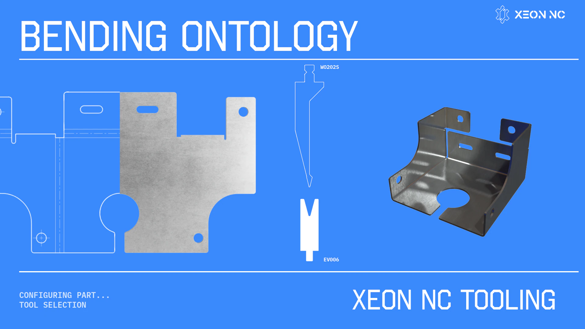
An "ontology" is simply the shared vocabulary that lets a designer and a machine agree on exactly what a bend is. Get the words right and the geometry follows — get them wrong and you ship a flat pattern that folds into the wrong part.
This guide defines the core bending terms the same way you'll see them in our instant quoting platform and on a press brake controller, then connects each one to the actual K-factor, radius, tooling, and bend deduction values we use in production. Use the material lookup tool below to pull the exact numbers for the material and thickness you're designing in.
The Bending Vocabulary
These are the building blocks of every formed part. Each card explains the term, its common abbreviation, and how it affects your design.
Flat = A + B − BD. Listed per angle in the tool below.K = t / MT. It's the single most important constant for accurate flats. Each material/temper has its own — see the tool.0.63 × die opening. Designing below it risks a malformed or unsafe bend.V ≈ 8 × thickness from a 5-die TRUMPF set.What Is Bend Deduction?
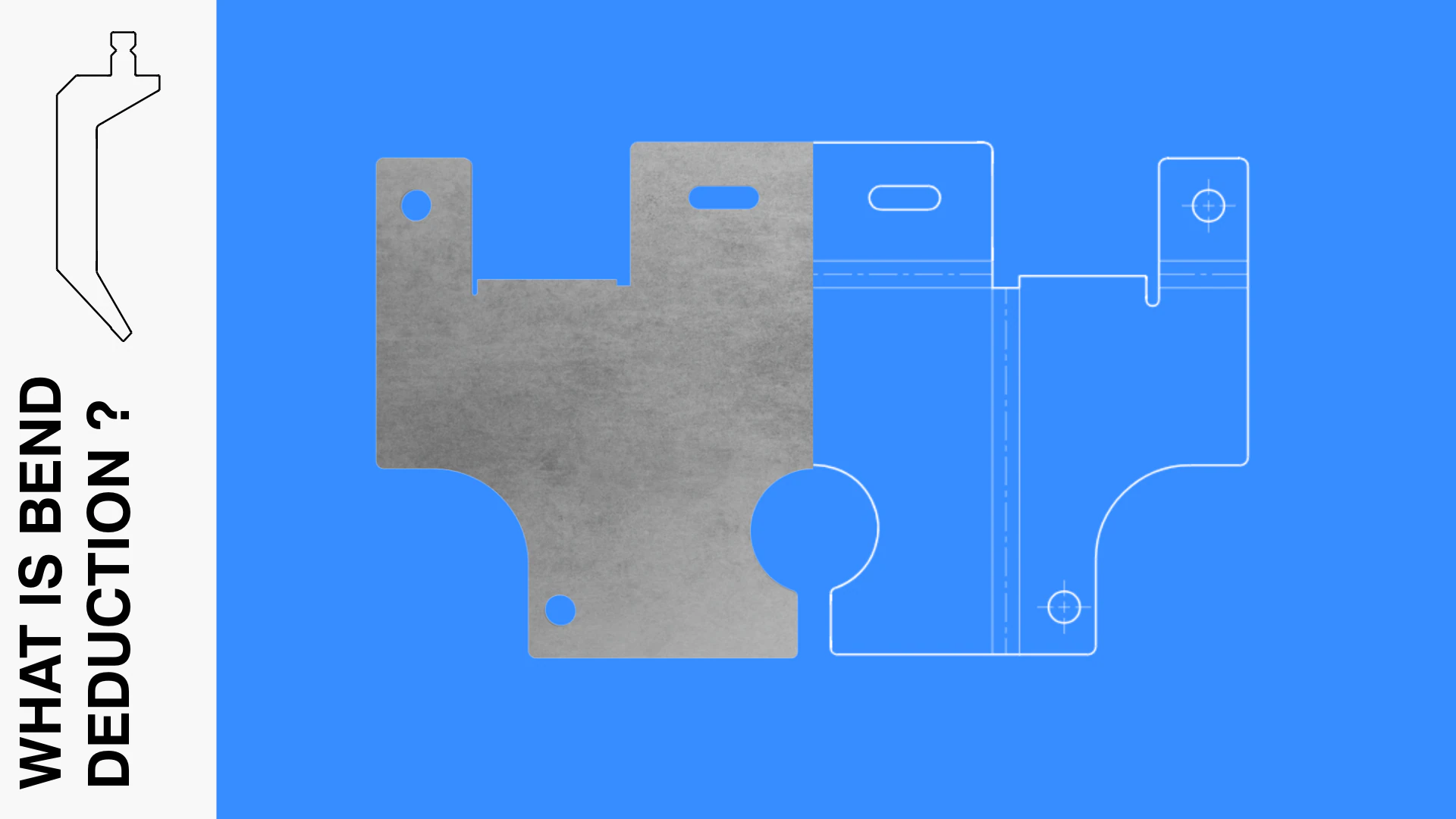
Bend deduction is the bridge between the part you model in 3D and the flat blank our laser actually cuts. When sheet metal bends, the outer surface stretches and the inner surface compresses, so the developed (flat) length is shorter than the sum of the outside leg dimensions. Bend deduction is exactly how much shorter.
Minimum Formed Flange
The minimum formed flange (or minimum leg length) is the shortest flange the press brake can reliably form. The flange has to bridge the V-die opening with enough material on both shoulders for the die to support it. Go shorter and the part slips into the die, producing a rolled, malformed, or dangerously launched bend.
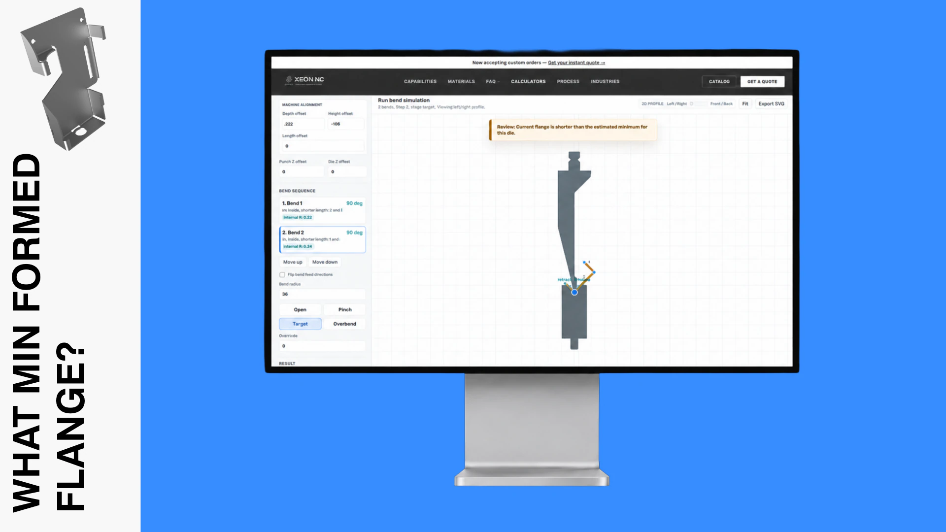
Because it scales with the die — and the die scales with thickness — the minimum flange grows as material gets thicker:
- Rule of thumb: minimum flange ≈
0.63 × V-die opening, where the V-die is about 8× the material thickness. - Thin sheet (24–16 ga): minimum flange around 0.20″–0.30″.
- Heavier plate (3/16″–1/4″): minimum flange climbs past 0.74″–1.24″.
The exact minimum flange for your chosen material and thickness is shown in the lookup tool below.
Bending Specifications Per Material
Select a material and thickness to pull its TRUMPF tooling assignment, K-factor, inside radius, minimum formed flange, and air-bend deduction at every angle. These are the same reference figures we form to in production — verify on a test bend before committing critical flats.
K-source family indicates the calibrated material whose K-factor was applied. Alloys without direct data (6061, 7075, 1100, Corten, AR500, spring steel) are proxied to the closest family — see the flag on each card. Tooling: 5-die TRUMPF set, V-die ≈ 8× thickness, air bend, dimensions in inches.
Bend Deduction & Allowance Charts
The full reference tables, the way you'd pin them up next to the brake. Pick a material, then read bend deduction (or bend allowance) straight off the row for your thickness and the column for your angle. These are computed from our actual TRUMPF tooling — the same numbers behind the lookup tool above.
Flat = A + B − BD. Bend allowance is the developed length of the bend itself. Both assume air bending at the inside radius and K-factor shown for that gauge.
Designing Your Flat With This Data
Putting the vocabulary and the numbers together, here's the order of operations for a clean first-article part:
- 1. Pick material & thickness — this fixes your V-die, inside radius, K-factor, and minimum flange in one move. Look them up above.
- 2. Check every flange against the minimum formed flange. Lengthen any leg that falls short, or plan a secondary operation.
- 3. Apply bend deduction per bend at the actual angle you're forming to develop the flat pattern. Multiply by the number of bends.
- 4. Keep features clear of the bend — hold holes and slots back at least
2× MT + IRfrom the tangent line (see our Bend Affected Zone guide). - 5. Add bend reliefs wherever a bend terminates mid-sheet, at least 1× thickness wide.
- 6. Specify the inside radius on your drawing — don't leave it to chance. The tool gives you the radius our tooling actually produces.