Our Press Brake Tooling Library
Every punch and V-die we run on the Xeon NC press brake, the material thickness each die covers under the 6–12 die-width rule, and the full technical data for each WILA OW / EV tool — so you know your part can be formed before it is ever quoted. Dimensions show in inches by default; flip any toggle to switch the whole page to millimetres.
Bend quality is decided by the tool stack, not the part. The V-die opening sets the radius, the tonnage, and the smallest flange you can form; the punch sets the angle you can reach and whether it clears the part on the way down. This page is the live inventory of what is physically in our tool cabinet — and exactly which gauge each piece is built to form.
The dies below are WILA / Trumpf-style EV bottom tools and the punches are OW top tools, all ground from 42CrMo4 tool steel and induction hardened to ~60 HRC. Match your material thickness to a die using the rule in the next section, then confirm the whole stack on our 2D Bend Check — it renders these exact tool profiles against your flat pattern.
The 6–12 Die-Width Rule
The single rule that maps a die to a thickness: the V-die opening should be 6 to 12 times the material thickness. Thin or soft material sits at the low end of that range; thick or high-strength material needs the wide end to avoid cracking the outer fibre and to keep tonnage in check.
So every die owns a thickness band: from V ÷ 12 at the thin end to V ÷ 6 at the thick end. Run thinner than V ÷ 12 and the part over-bends into a sharp, unrepeatable radius; run thicker than V ÷ 6 and you risk outer-fibre cracking and over-tonnage. The chart below plots that band for every die we own.
Thickness Coverage Map
Each bar is the band a die can form (V ÷ 12 → V ÷ 6). Hover a bar for its exact range, and switch units with any toggle on the page. Together our five dies cover roughly 0.03″–0.33″ (0.7–8.3 mm) — 22 ga through 5⁄16″ plate.
Bands are the geometric 6–12 window. The thin bars (EV002) overlap into the next die up, which is normal — pick the narrower V for a tighter radius, the wider V for lower tonnage.
How to Read a Tool Card
Each tool below carries a Technical data grid in the same layout as our shop tooling app. The geometry values — V-opening, angle, tip radius, height, tonnage — are read directly from the tool's CAD file, and follow whichever unit the page toggle is set to (inches by default).
Lower Tooling — V-Dies
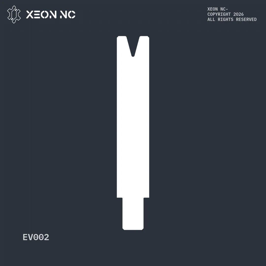
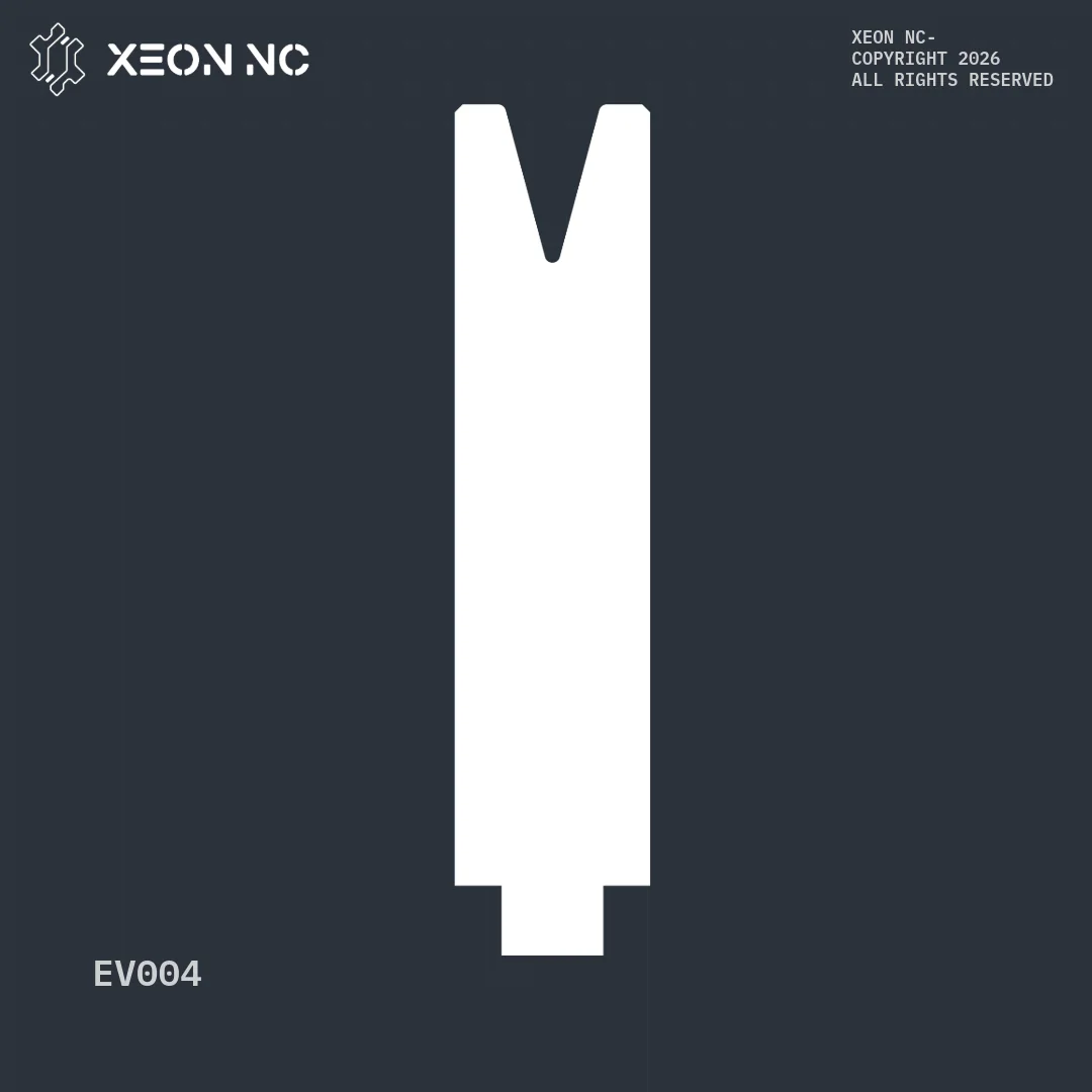
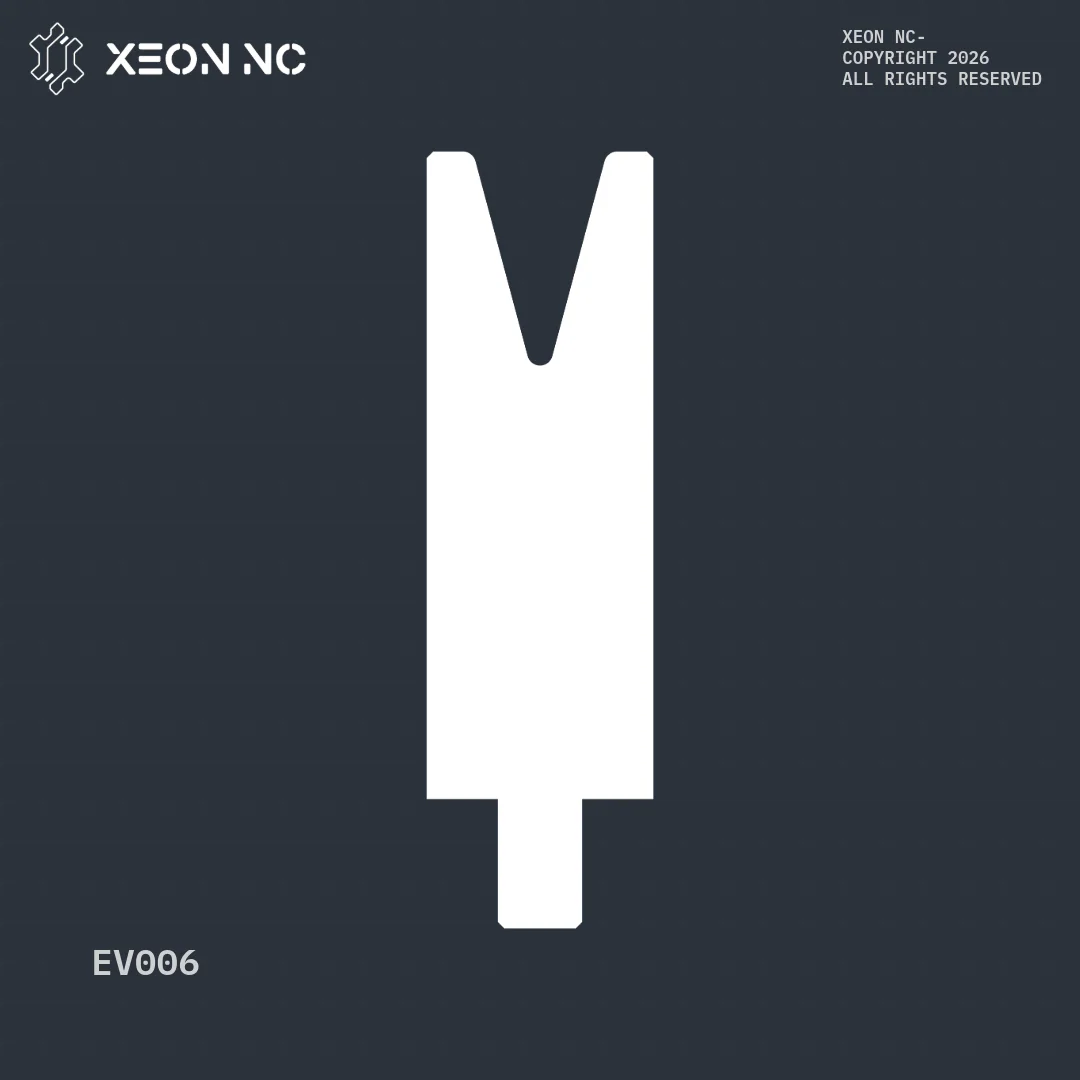
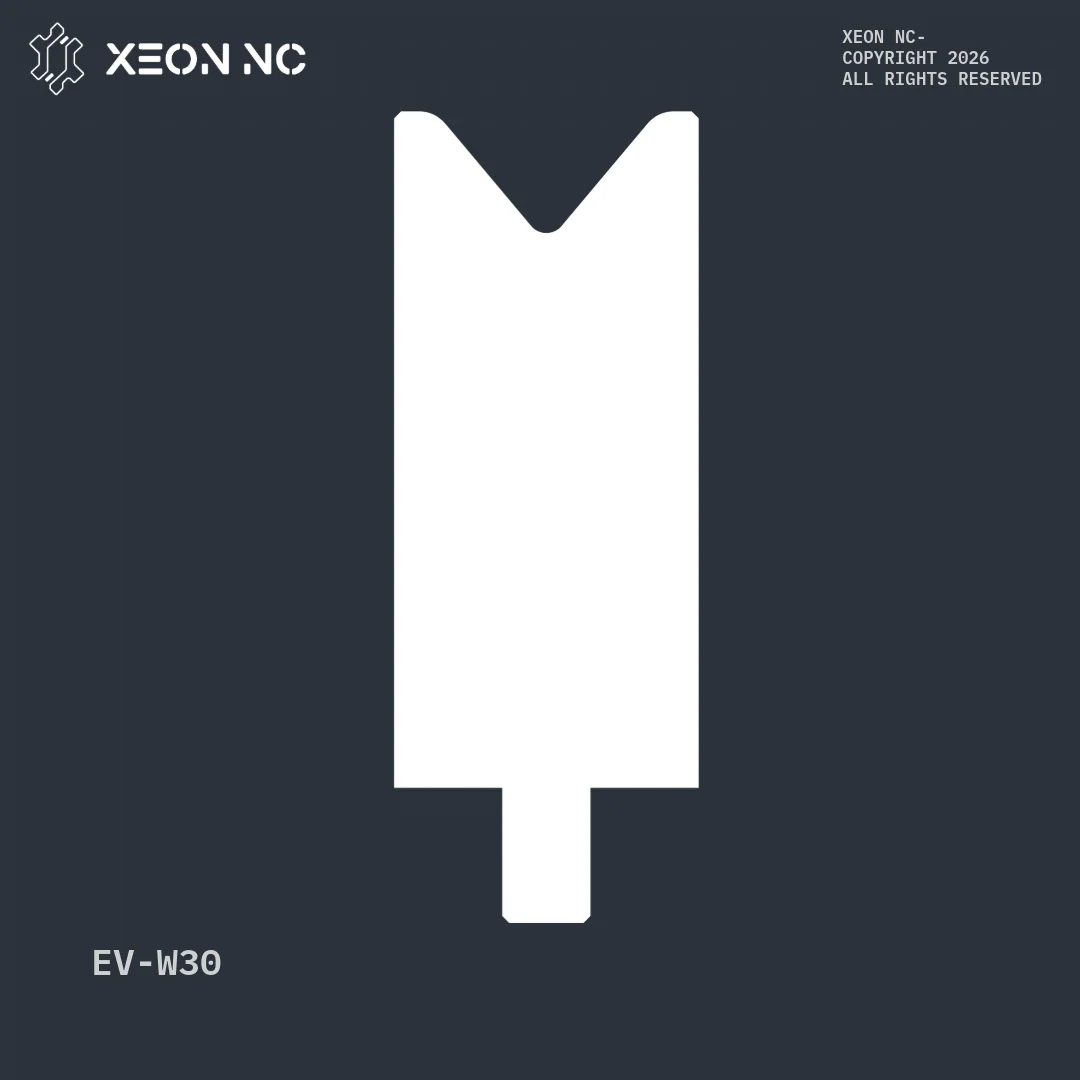
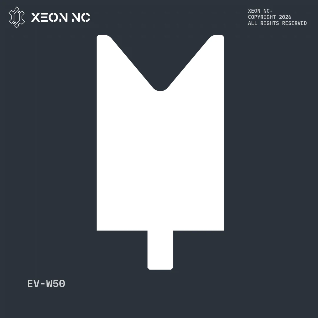
Single-V air-bending dies, WILA / Trumpf EV style, seated in the standard DTrumpf lower clamp. The die opening sets the radius and the tonnage; the die angle (30° or 80°) sets how acute a bend it can clear.
Upper Tooling — Punches
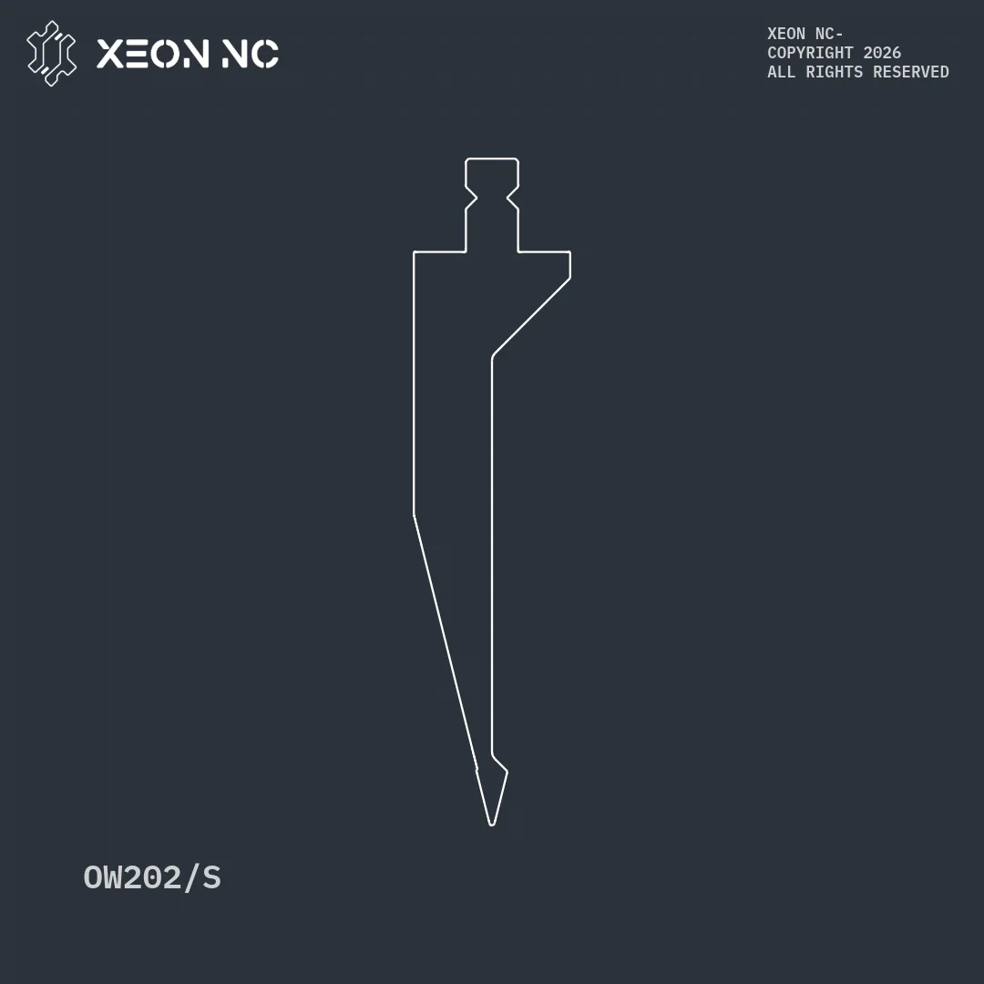
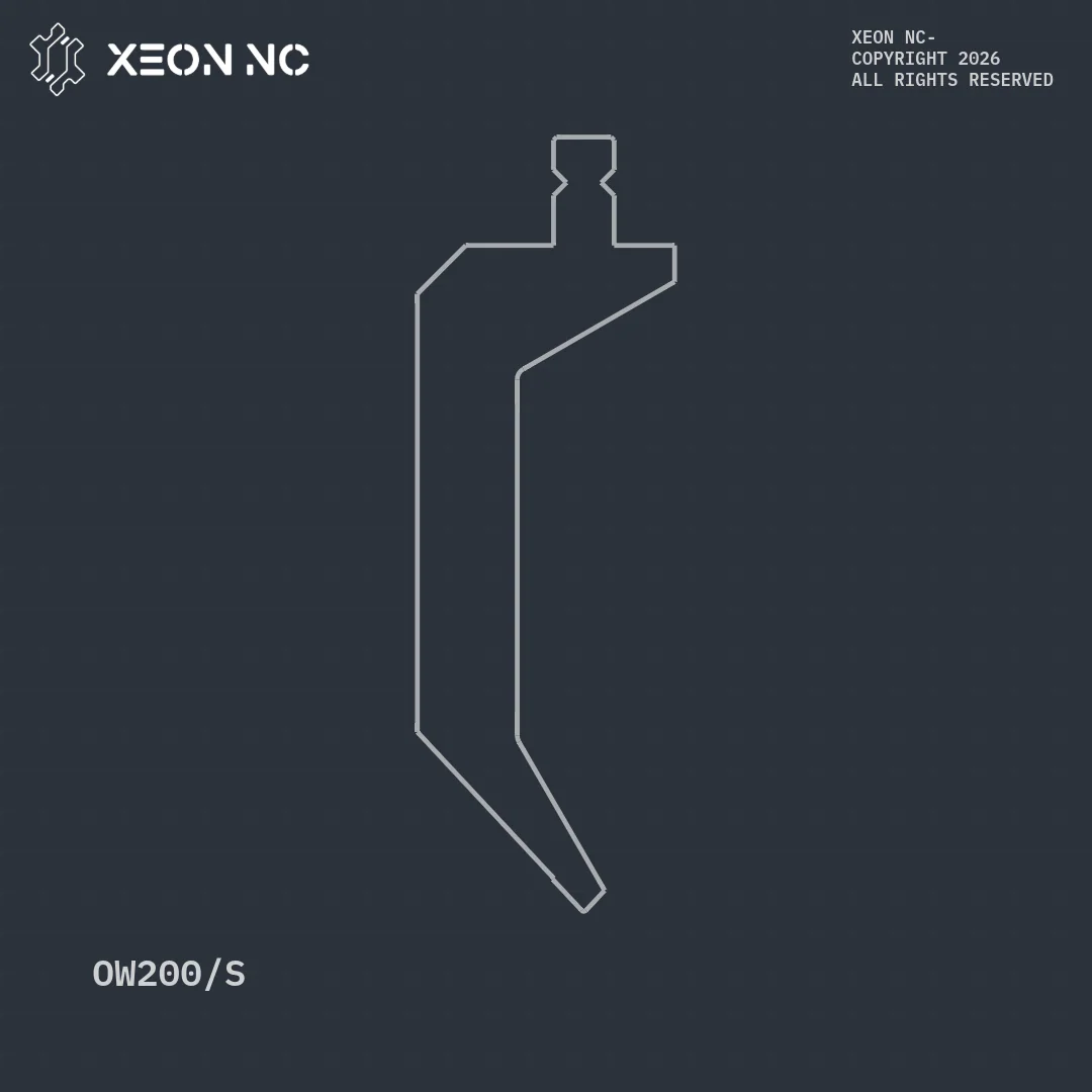
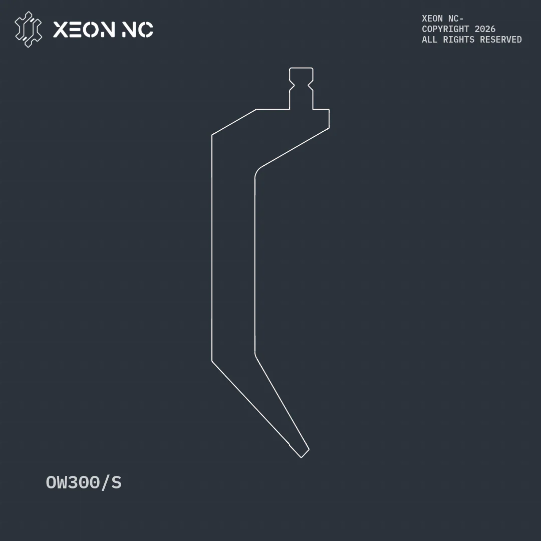
OW top tools seated in the PTrumpf upper clamp. A punch is not chosen by thickness — it is chosen by three things: the tip radius (the smallest inside radius it can press), the included angle (how acute a bend it can reach), and the height (how tall an adjacent flange it can clear without colliding). Pair any of these with the die that matches your gauge.
Full Reference Table
V-Dies — thickness coverage
| Die | V-opening | Angle | Radius | Thickness (6–12) | Gauge |
|---|---|---|---|---|---|
| EV002 | 30° | R1 | 22 – 16 ga | ||
| EV004 | 30° | R1 | 19 – 14 ga | ||
| EV006 | 30° | R2 | 14 – 10 ga | ||
| EV W30/80 | 80° | R5 | 12 – 7 ga | ||
| EV W50/80 | 80° | R5 | 8 ga – 5⁄16″ |
Punches — selection by geometry
| Punch | Tip R | Angle | Height | Type | Rated load |
|---|---|---|---|---|---|
| OW202/S | R1 | 28° | Pointed / acute | 600 t/m | |
| OW202/K | R1 | 28° | Pointed / acute | 600 t/m | |
| OW200/S | R1 | 86° | Gooseneck | 800 t/m | |
| OW300/S | R1 | 86° | Gooseneck | 800 t/m | |
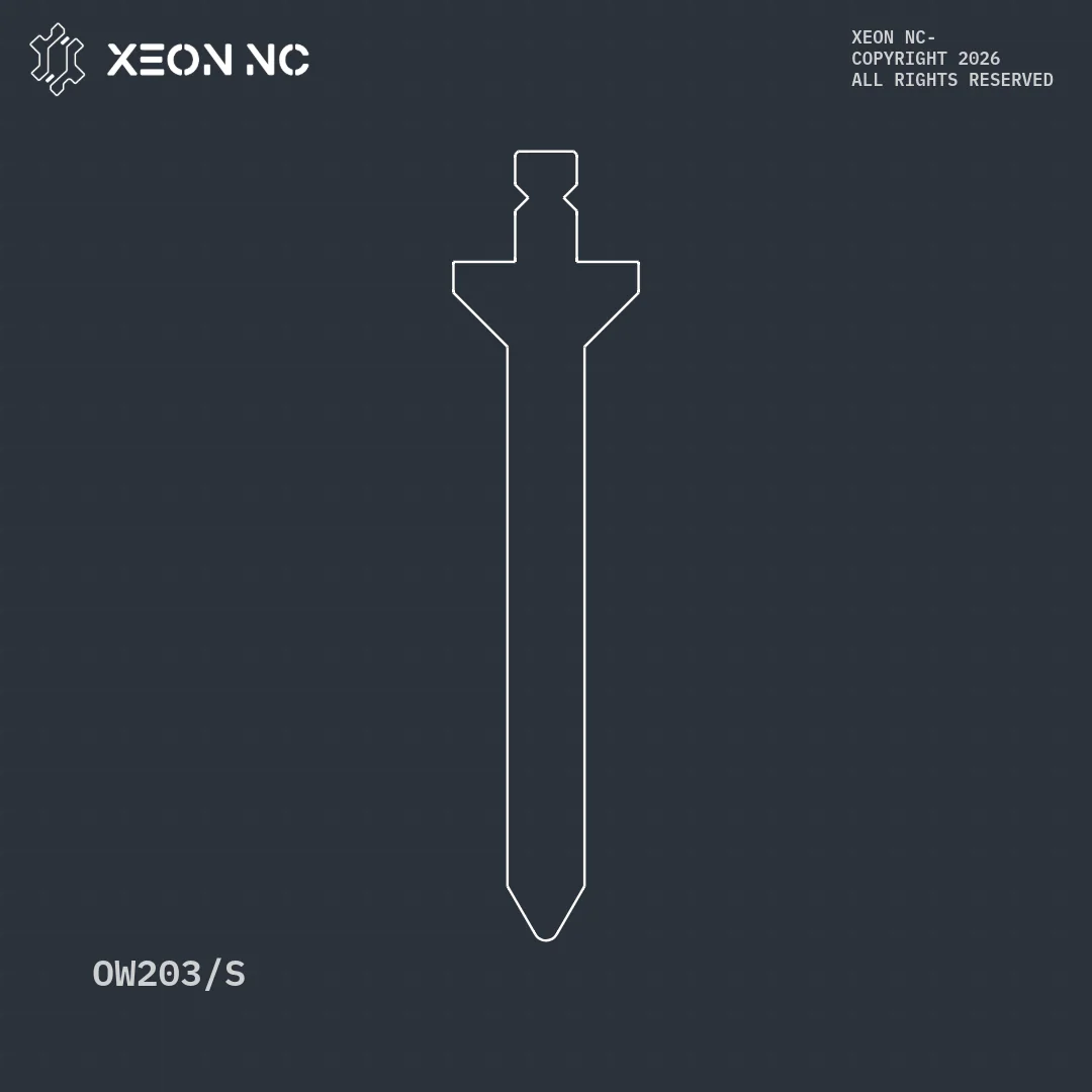
| OW203/S | R4 | 60° | Straight / large-R | 2500 t/m |
Geometry figures are read from each tool's CAD file. Gauge equivalents are nominal steel; aluminium and stainless shift the band toward the tight and wide ends of the 6–12 window respectively.