Reverse Bend Clearance Checker
A Xeon NC design tool — enter your base dimension and return flange height and see whether our press brake tooling can actually reach the bend. The envelope is computed live from the real punch profiles in our bend simulator, not from a rule of thumb.
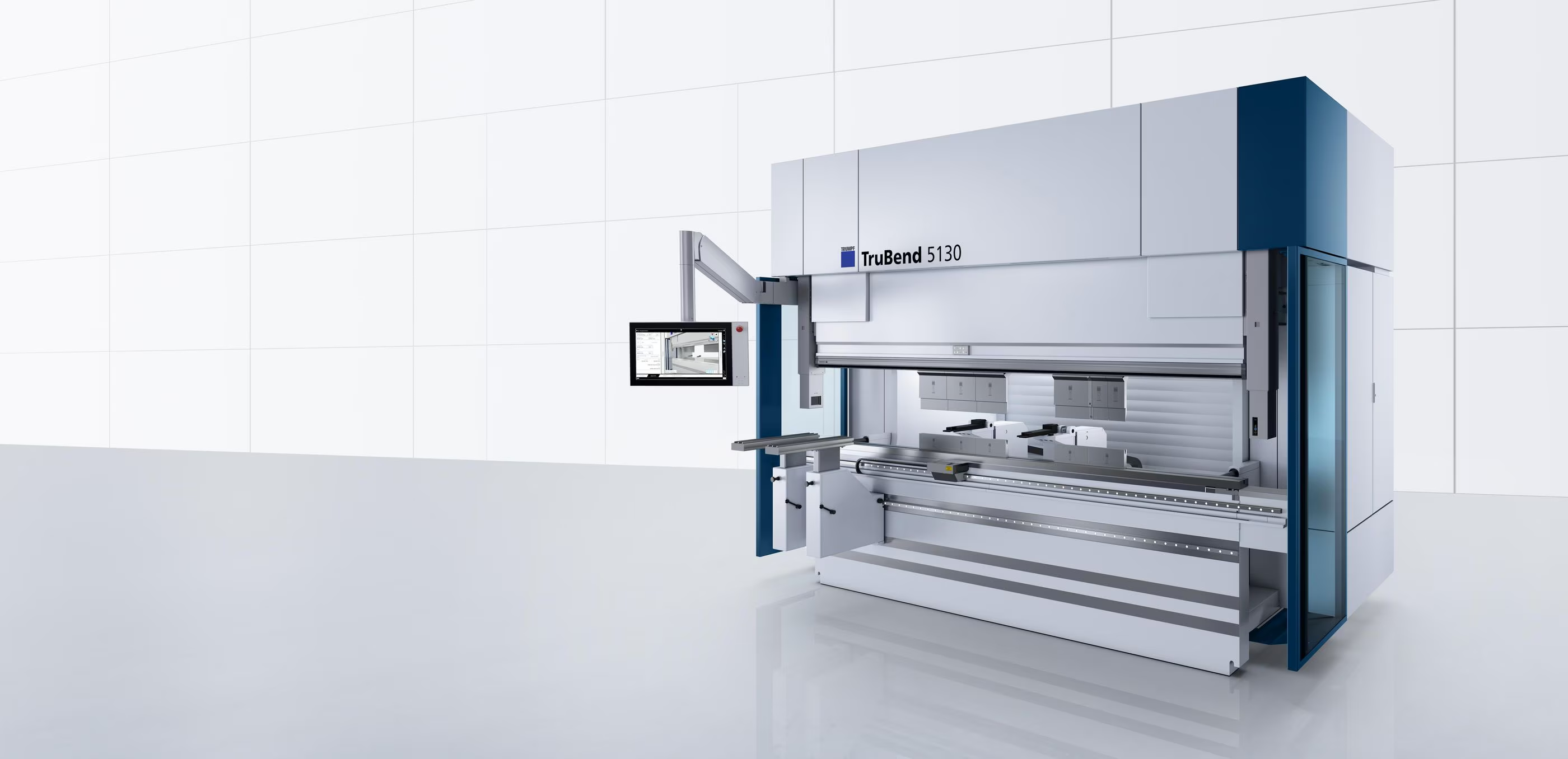
Every bend after the first one has to fit around metal that is already standing up. The punch is a solid steel wedge roughly 220 mm tall — whether your part clears it is pure geometry, and it is decided long before the job reaches the brake.
A reverse bend is any bend that has to be formed while a previously formed flange is standing up next to the punch. Channels, trays, offsets, Z-sections, return flanges and hems all create the same situation: by the time the last bend goes in, part of your part is already occupying the space the tool needs.
The limit is not tonnage and it is not the material. It is that a press brake punch is a solid piece of 42CrMo4 about 220 mm tall, and the standing flange either fits alongside it or it does not. If it does not, the part cannot be made in that bend sequence — no amount of clever programming helps, because there is no room for the steel.
What makes this hard to eyeball is that the part moves during the bend. At the bottom of the stroke the base of the part is folded into a V around the punch tip, so the two legs are tilted upward — roughly 45° each for a 90° bend. Every flange already standing on those legs gets swung up and inboard, toward the punch body, exactly when clearance is tightest. A flange that looks like it has an inch of room in the flat CAD view can be touching the tool at the bottom of the stroke.
Reverse Bend Clearance Checker
Punch Clearance — Return Flange
| Punch | Tip R | Angle | Height | Max flange | Verdict |
|---|
bend-simulator/tooling-geometry.js — the same DXF-traced punch and die profiles our 3D bend simulator draws with. Material, gauge, die and default punch come from bend-tables.js, the table our programmers bend from. This is a geometric screen, not a quote: send the part and we will confirm against the real bend sequence.
Reading the Envelope
The chart on the right of the checker is the useful output. The horizontal axis is your inside base dimension — how much flat sits between the new bend line and the flange that is already formed. The vertical axis is the tallest that already-formed flange can be. Each curve is one of our punches.
Anything under a curve can be formed with that punch. Anything above it cannot: the flange would be standing in the tool's way at the bottom of the stroke. Your part is the black dot.
Three features of the curves are worth understanding, because they explain most of what happens to real parts.
- Near the origin, every curve collapses. With a short base dimension the flange is close to the punch tip, where the tool is a solid wedge. There is no relief available that close in — the punch has to be that shape to press the radius. This is why a narrow channel with tall legs is the hardest thing to ask for.
- Then the curves jump. Once the base dimension is past the widest point of the tip wedge, the flange clears into the relieved section of the punch and the ceiling suddenly becomes the full working height of the tool. The jump is a real cliff edge, not a gradual improvement, and it lands in a slightly different place for every punch.
- At the far right, the curves flatten or dip. The top of the tool is not straight — the head flares out where it seats into the clamp. A very tall flange a long way out can catch that flare, which is why the curves stop rising and in one case turn back down.
Where the Limit Comes From
The model is deliberately simple, which is what makes it trustworthy. There are only four moving parts.
Step 2 is the one people miss. In the flat CAD view the base is horizontal and the return flange points straight up, comfortably clear of everything. At the bottom of the stroke that base is folded into a 90° V, both legs are at 45°, and the return flange has rotated 45° toward the punch along with the leg it sits on. For a 90°/90° part this works out to a memorable rule of thumb: the flange can be about as tall as the base is long, before you consider which punch is in the machine.
Step 4 is why acute angles hurt twice. An already-formed flange at 60° instead of 90° does not just stand up — it leans back over the base, directly into the space the punch body needs. Change the return flange bend angle in the checker from 90° to 60° and watch the ceiling drop.
Everything the model needs about the tool comes out of the traced profile: the wedge half-angle near the tip, the tip radius, where the relief starts, how tall the relieved section is, and where the head flares. None of it is estimated.
Our Punch Library, in Clearance Terms
The five punches in our library, described by what they can reach around rather than by what radius they press. Full geometry and photos are in the Press Brake Tooling Library; these are the numbers that decide a reverse bend.
| Punch | Tip R / angle | Relief starts at | Relieved height | What it is for |
|---|
Relief starts at is how far the flange has to be from the punch centreline before it stops fouling the tip wedge and gets into the relieved section. Relieved height is how tall it can then be before it reaches the tool head. Both are measured off the traced profile.
What this means in practice
- OW202/S is the default for most of our gauges and is already an offset tool — its body sits back behind the tip line, which is why it handles ordinary return flanges without a tooling change.
- OW200/S is the gooseneck. Its 86° tip is fatter close in, so it is worse than the acute punch at very small base dimensions, but its throat clears far more once you are past it. It is the tool for a tall return flange on a reasonable base — and, as covered below, the wrong tool when flanges stand on both sides.
- OW300/S is the same gooseneck 80 mm taller. This is the deep-box and deep-tray tool — the only one that clears flanges taller than about 190 mm.
- OW203/S is the heavy R4 punch for plate. Its 60° included angle makes it the worst of the set for clearance, which is the trade for pressing a soft radius in 1/4″ material.
- OW202/K is the short 120 mm body. Useful for shallow parts, but its low head means tall flanges run out of room sooner.
One Flange vs. Two: Why Hat Sections Are Harder
Switch the checker between Formed flange on one side and Formed flange on both sides and the ceiling drops sharply. Understanding which of the two your part is doing matters more than any other input on the panel.
First, which case are you in?
The check is about flanges that are already formed when the current bend goes in. The material on the far side of the bend line being formed right now is not a problem — it is wrapping the punch tip, which is what it is supposed to do.
- One side is the normal case, and it covers more parts than people expect — including the last bend of a plain U-channel. When you form the second leg of a channel, only the first leg is standing; the second one is being created by the stroke you are in.
- Both sides is the harder case: a bend that goes in between two flanges that already exist. Hat sections, top-hat stiffeners, trays already flanged at both ends, and any part where the bend order forces the middle bend to come last.
Why the second flange costs so much
Our punches are relieved on one side — the body is set back behind the tip line on the working side and full width on the other. With one formed flange we simply turn the relief towards it and you get the generous curve. With flanges on both sides only one of them can be in the relief. The other is up against the full body of the tool, and that side sets the limit.
The gooseneck punches show this most dramatically, and in a way that inverts the usual advice. An OW200/S has an 86° included tip — almost the same angle as the 90° V your part is folded into at the bottom of the stroke. On the relieved side that hardly matters. On the unrelieved side the punch flank ends up running very nearly parallel to the leg of your part, a couple of degrees apart, so the already-formed flange on that side is effectively touching the tool from the moment it exists. For a two-flange bend the gooseneck is the worst tool in our library, and the acute 28° OW202/S — whose flank sits far inside the V — is the best. The checker's table shows this directly.
If It Doesn't Clear
A red verdict is not the end of the part. In rough order of how little it costs you:
- Grow the base dimension. The cheapest fix by a wide margin, and often invisible to the function of the part. Because the curves have a cliff edge, a very small increase can take you from impossible to comfortable — the checker will tell you the minimum base dimension for your flange height.
- Shorten the return flange. Equally cheap if the flange is there for stiffness rather than for a fastener.
- Open the return flange angle. If the already-formed bend is acute, bringing it to 90° stops it leaning into the tool and buys a surprising amount of room.
- Let us change the punch. Free, and often enough on its own — the checker shows which of the five clears. A gooseneck or the tall OW300/S may pick up a part the default tool cannot.
- Re-order the bends. Sometimes forming the return flange last instead of first removes the conflict entirely. This is our problem to solve, not yours, but it is worth knowing it exists as an option.
- Split the part. If nothing clears, the geometry becomes two parts and a joint. Better to find that out now than after tooling up.
Model Assumptions
Stated plainly, so you know what the green verdict is and is not promising.
- It checks the punch only. Interference with the die, the backgauge fingers, the machine bed or the operator's hands is not modelled. Downward-facing flanges near the die shoulder are the usual case this misses.
- It checks the part against the tool, not against itself. Part-on-part collision is a separate question with its own guide and 3D viewer.
- The corner is idealised as sharp. The real inside radius starts the flange a little further from the bend line, so the true clearance is marginally better than reported. Erring conservative is deliberate.
- The flange is checked on its inside face. Material thickness is drawn in the cross-section but the binding surface is the face towards the tool, which is the one that touches.
- Bottom of stroke, fully formed. The check is made with the part at its final angle and the punch at depth. The bend is a continuous motion and clearances change through it; a part that only just clears at the bottom of the stroke deserves a real simulation, which is what our programmers run.
- Tools are treated as flippable. We orient the relief towards the flange, which is what the shop does. OW203/S is symmetric so orientation is irrelevant to it.
- Profiles are 2D cross-sections. Segmented tooling, tool gaps along the bend line and features that vary across the width of the part are outside this model.
Within those bounds the numbers are exact geometry off our real tool profiles rather than a published rule of thumb. Treat a comfortable green as a strong signal, a tight amber as a conversation, and a red as a design change.