01 / SHAPE
The edge creates the form
Flat, spherical, angled, radiused, and disk-shaped cutters leave fundamentally different geometry.
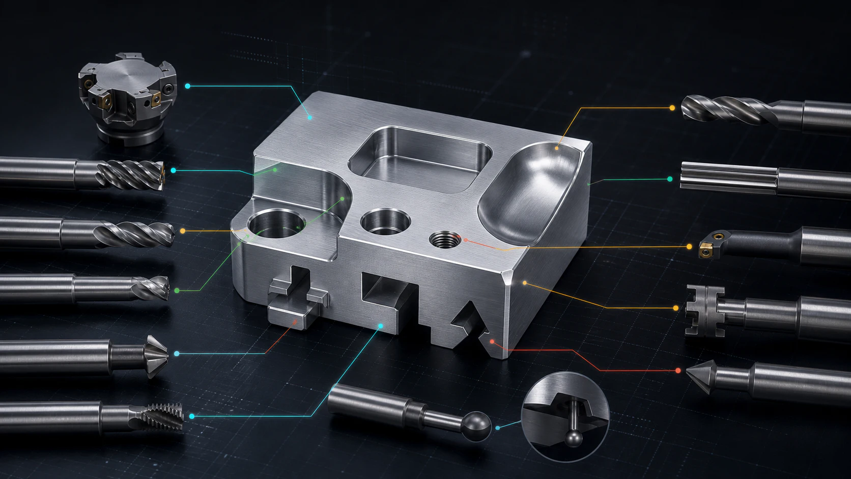
End mills, face mills, drills, boring tools, thread mills, slot cutters, dovetail cutters, and lollipop tools—and the features each one can physically reach.
Flat, spherical, angled, radiused, and disk-shaped cutters leave fundamentally different geometry.
A cutting edge may reach the feature while its neck, shank, collet, or spindle still collides.
Reach increases flexibility. Deflection, chatter, taper, and finish risk grow quickly with stickout.
Tool geometry, path, material, runout, workholding, coolant, and inspection act together.
A CNC machine can move through an extraordinary range of coordinates. The cutting tool determines which of those coordinates can actually remove material.
A square end mill leaves a flat floor and radiused inside corners. A ball-nose tool traces a smooth three-dimensional surface. A drill advances axially to establish a hole. A face mill sweeps a broad plane. A keyseat cutter reaches sideways behind a wall. A lollipop cutter wraps cutting edges around a spherical head so it can finish geometry hidden from a conventional end mill.
This is why machinability cannot be decided from machine travel alone. The tool diameter, neck, flute length, overall reach, holder, approach direction, material, and required finish all have to fit the feature at the same time.
Catalog names help select a family. Physical dimensions determine whether a specific cutter can enter, clear, cut, evacuate chips, and remain stable.
Controls corner radius, slot width, contact area, rigidity, and minimum opening.
The fluted length available to engage the wall or feature without rubbing the shank.
Determines how deeply the cutting diameter can extend past nearby geometry.
Balances cutting edges, core strength, chip space, feed, and finish.
Square, corner-radius, ball, tapered, angled, disk, spherical, or formed.
More reach is not free capability. A longer, smaller tool behaves like a more flexible cantilever. If the feature can accept a larger internal radius, a shorter depth, a different setup, or a relieved wall, the process often becomes faster, quieter, more accurate, and less expensive.
A production program normally uses several tool families. Roughing, finishing, holemaking, edge treatment, threading, and hidden features reward different geometries.
A large-diameter cutter with replaceable inserts sweeps across the top of the workpiece. It is optimized for efficient planar stock removal and broad, consistent faces.
The general-purpose pocket, wall, shoulder, profile, and slot cutter. Center-cutting designs can ramp or helix into material; others require an entry path.
A small radius connects the tool's end and side. The radius strengthens the cutting edge and intentionally creates a floor-to-wall fillet.
A hemispherical tip follows molds, organic surfaces, fillets, and 3D contours. Surface finish depends on stepover, tool angle, runout, and the local effective diameter.
An axial tool that establishes round holes quickly and evacuates chips through its flutes. Spotting, geometry, coolant, depth, and material influence entry and straightness.
A reamer removes a small, controlled allowance to size and finish a prepared hole. A boring tool can correct size and position by cutting the bore from a defined spindle path.
An angled cutting edge breaks sharp corners, creates countersinks, prepares weld edges, and machines specified chamfers around holes and profiles.
A thread-profile cutter follows a helical path to generate internal or external threads. One cutter may cover multiple diameters at the same pitch.
A disk-like head on a smaller neck enters through an opening and cuts laterally behind the wall. Keyseat or Woodruff-style cutters also create controlled groove widths.
An angled form cutter creates locking grooves, guide features, workholding interfaces, and tapered undercuts at a defined included angle.
A spherical or near-spherical cutting head wraps cutting edges far around the tool. It profiles hidden surfaces, deburrs complex intersections, and reaches behind curved geometry.
A thin circular cutter creates deep, narrow slots with less material removal than an end mill. It is useful for split features, tabs, and cutoff-style operations.
Choose a feature below to see the primary tool family, common supporting operations, and the design constraint that controls access.
Create a large, consistent datum or top surface with efficient radial coverage.
The whole assembly—cutting diameter, neck, shank, holder, spindle, workpiece, and fixture—must survive every programmed position.
If a mating component truly requires a square corner, consider corner reliefs, dog-bone geometry, broaching, EDM, an assembly change, or another process. Calling out “sharp” does not change the circular cutter.
The right program does not ask one cutter to do everything. It assigns each stage to a tool that can remove material efficiently and leave the next operation in control.
Tool choice also depends on the workpiece material. Aluminum favors sharp edges and generous chip space. Stainless steel demands control of heat, work hardening, and rubbing. Hardened steels need edge strength, coatings, stable engagement, and rigid setups. Plastics may need high rake, low heat, and burr control. The same nominal feature can require a different cutter geometry in a different material.
The best CNC design protects what matters while allowing practical tools, approaches, and inspection methods everywhere else.
An end mill is a versatile smaller-diameter cutter used for pockets, slots, walls, profiles, and local faces. A face mill is a larger indexable cutter optimized to create broad flat surfaces efficiently.
It depends on the undercut. T-slot or keyseat cutters machine horizontal grooves, dovetail cutters create angled undercuts, and lollipop-style undercutting end mills reach behind curved or complex surfaces.
An end mill can interpolate a hole and can improve its location, but critical size, roundness, straightness, and finish may require boring or reaming after an undersize hole is established.
A rotating cylindrical cutter cannot create a perfectly sharp internal corner. The smallest practical radius is controlled by cutter size, feature depth, reach, deflection, material, and finish.
It is common, but not universal. Bull-nose, tapered ball, barrel, lens, and other profile tools may improve reach, finish, or cycle time depending on the surface and machine kinematics.
No. A lollipop cutter has a spherical or near-spherical cutting head for complex undercut profiling and deburring. A T-slot or keyseat cutter uses a disk-like cutting head to create a controlled lateral groove.
Yes. Upload the model and include a drawing for critical tolerances, threads, datums, surface finish, and inspection. Applications engineering can review access, tool reach, internal radii, undercuts, workholding, and the likely manufacturing sequence.
Upload a STEP model with a PDF drawing for critical features. Xeon NC can review the cutter access, workholding, machining sequence, tolerances, threads, finishes, and inspection requirements behind the quote.
Upload your files →