FORM / 01
1.000 ±0.001
Equal bilateral
Variation is allowed equally in both directions. Limits: 0.999 to 1.001.
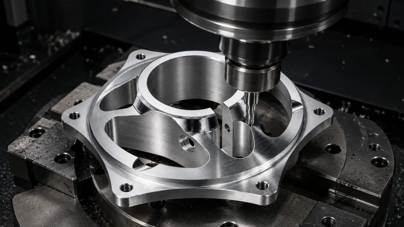
The nominal dimension states the design intent. The tolerance defines the manufacturing zone. CNC machining is the controlled work of keeping every critical feature inside it.
Before metal enters a vise, a drawing or model has already decided what the part is allowed to become.
The CAD model describes an ideal object. Real manufacturing operates in variation: stock is not perfectly uniform, cutters wear, fixtures deflect, material moves as stress is released, temperature changes dimensions, and measurement itself carries uncertainty. Tolerancing is the language that connects the ideal object to the physical process.
A good drawing does not ask the shop to create mathematical perfection. It identifies the boundaries inside which the part will assemble, move, seal, locate, and survive. It separates critical interfaces from ordinary geometry. It tells production where variation is harmless and where it is not.
“To the thousandth” is therefore incomplete on its own. Does it mean a dimension shown to three decimal places? A total tolerance band of 0.001 inch? A bilateral tolerance of ±0.001 inch? A one-sided fit limit? The drawing must remove the ambiguity.
A nominal dimension names the intended size. The lower and upper limits define the sizes that can actually be accepted.
Consider a feature specified as 1.000 ±0.001 inch. The nominal is 1.000. The lower limit is 0.999. The upper limit is 1.001. The total legal manufacturing window is 0.002 inch—two thousandths—even though the tolerance is called “plus or minus one.”
A machinist will normally establish a process target that leaves margin on both sides of the actual limits. That target is often near the center of the zone, but it does not have to equal the printed nominal. Tool wear, coating growth, one-sided limits, or predictable process drift may justify targeting elsewhere inside the window.
The notation determines how the manufacturing window is positioned around the nominal.
Unilateral and limit dimensions are especially useful for interfaces that must never cross one boundary: a shaft that must not exceed a maximum, a hole that must not fall below a minimum, or a surface that will gain thickness during coating.
CNC machining is controlled material removal, but the programmed toolpath is only one element in the dimensional system.
A machine can position accurately and still produce a bad feature if the cutter deflects, the tool is worn, the stock moves, the fixture relaxes, or the inspection method measures the wrong characteristic. Finished-part capability belongs to the entire loop, not to one line in a machine brochure.
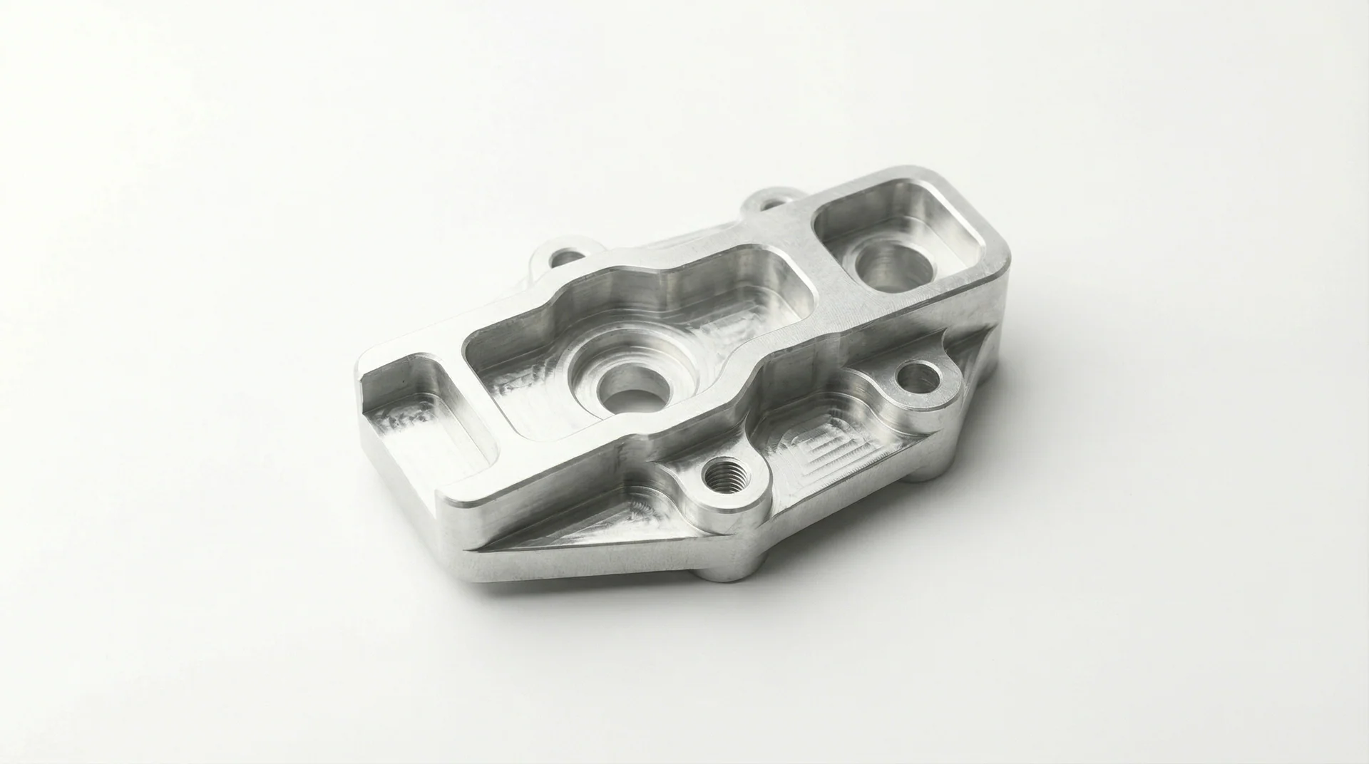
Xeon NC holds ±0.001 inch on critical features. General machined dimensions without an individual callout follow ISO 2768-1 medium unless the drawing or order specifies otherwise.
Tightening a dimension can change tool selection, sequence, number of setups, finishing strategy, temperature control, inspection frequency, gage selection, cycle time, and scrap risk. It can also restrict coating options because anodize, plating, paint, and heat treatment may change the final size.
The right approach is tiered: use a practical general tolerance for the drawing, then apply explicit tight limits only to the features that control fit or performance. A non-mating pocket floor does not need to cost the same as a bearing seat.
Smaller nominal dimensions receive a tighter—smaller—allowable deviation. Larger nominal dimensions receive a wider tolerance band.
Xeon NC uses ISO 2768-1 medium class (m) for general linear dimensions that do not carry an individual tolerance. The standard does not apply one universal plus-or-minus value to the whole drawing. It assigns a deviation by the nominal-size range of each dimension.
This stepped system reflects manufacturing reality without pretending that every feature needs the same precision. Be precise with the language: a tighter tolerance has a smaller allowed deviation; a wider tolerance permits more variation. “Higher tolerance” is ambiguous and should be avoided.
A bore can measure exactly 1.000 inch and still fail because it is tapered, out of round, angled, or in the wrong place.
Traditional plus-or-minus dimensions primarily control size and coordinate distance. Geometric Dimensioning and Tolerancing adds controls for form, orientation, location, profile, and runout. Datums establish the reference frame from which these relationships are interpreted and inspected.
Flatness, straightness, circularity, and cylindricity constrain a feature's own geometry without necessarily locating it.
Parallelism, perpendicularity, and angularity control how a surface or axis is oriented relative to a datum.
Position controls the location of holes, pins, slots, and other features relative to a datum reference frame.
Profile and runout can control complex surfaces or rotating relationships that a collection of linear dimensions cannot describe cleanly.
This is also how a drawing avoids tolerance-stack ambiguity. Repeated chain dimensions accumulate worst-case variation from link to link. Baseline dimensions or basic dimensions located from a functional datum can express the relationship the assembly actually cares about.
A tolerance is meaningful only when the feature can be measured with adequate resolution, repeatability, and a clearly defined method.
Measurement does not reveal an unknowable “true” value without uncertainty. It produces an estimate using a defined instrument, environment, operator, contact force, datum setup, and method. As the tolerance shrinks, the inspection system must become proportionally more capable and better controlled.
Temperature matters as well. Metals expand and contract. A warm part measured immediately after cutting may not represent its stabilized size. Tight work requires the manufacturing and inspection plan to account for thermal state instead of treating the last displayed digit as absolute truth.
The best tolerance is the widest one that still guarantees assembly and performance.
Upload your STEP file with a PDF drawing for critical tolerances, datums, threads, surface finish, and inspection requirements. We will machine the geometry and build the control plan around what matters.
Upload your files →