Deburring & Surface Finishing
Weber 1350 operations, part size rules, and finish selection — by Xeon NC Engineering
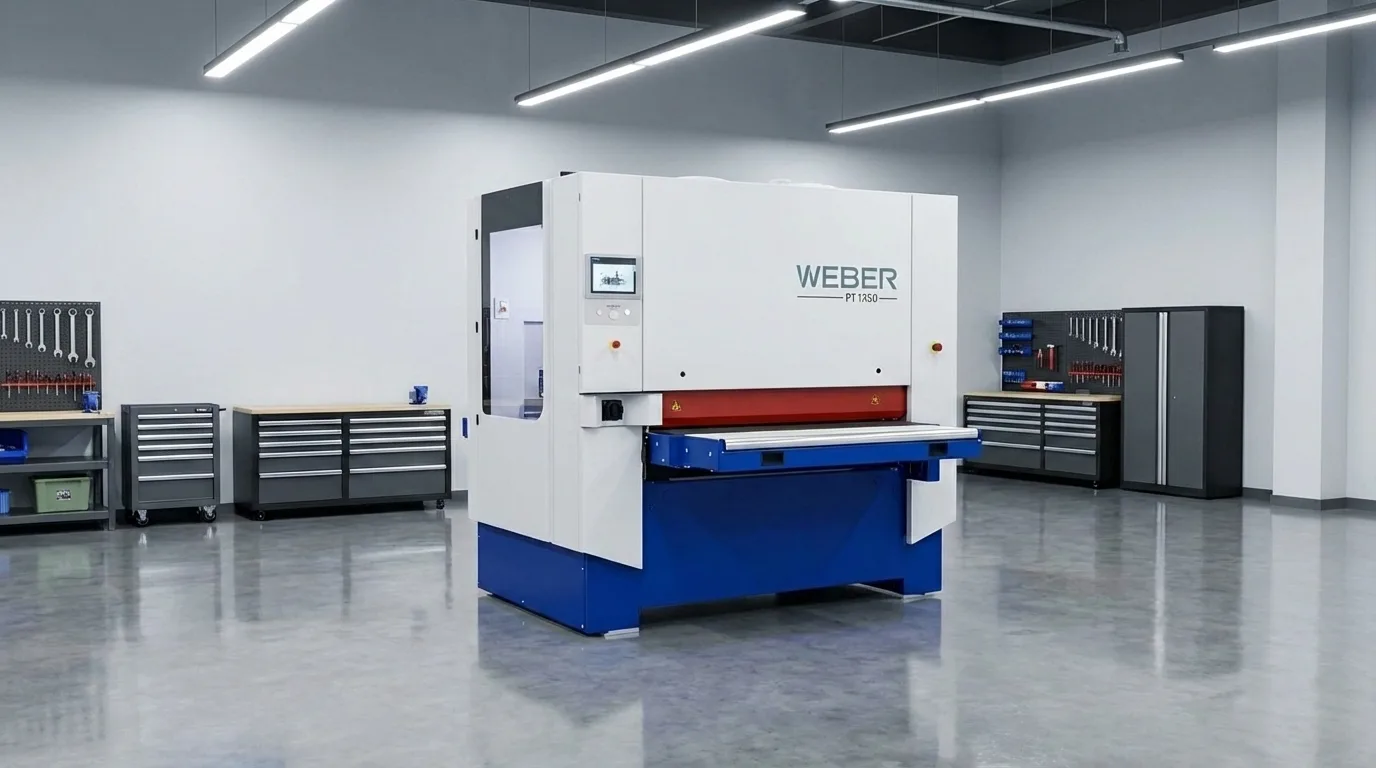
Every laser-cut, plasma-cut, or punched sheet metal part leaves the machine with burrs, sharp edges, and thermal oxide on the cut faces. Left untreated, these defects create assembly hazards, paint adhesion failures, and cosmetic rejection. Our Hans Weber 1350 through-feed deburring system eliminates all three — in a single automated pass.
This guide covers everything you need to know about how we deburr and finish your parts: the machine, its processing stations, the operations available to you, and the design rules that ensure your parts run cleanly through the system without issues.
The Weber 1350
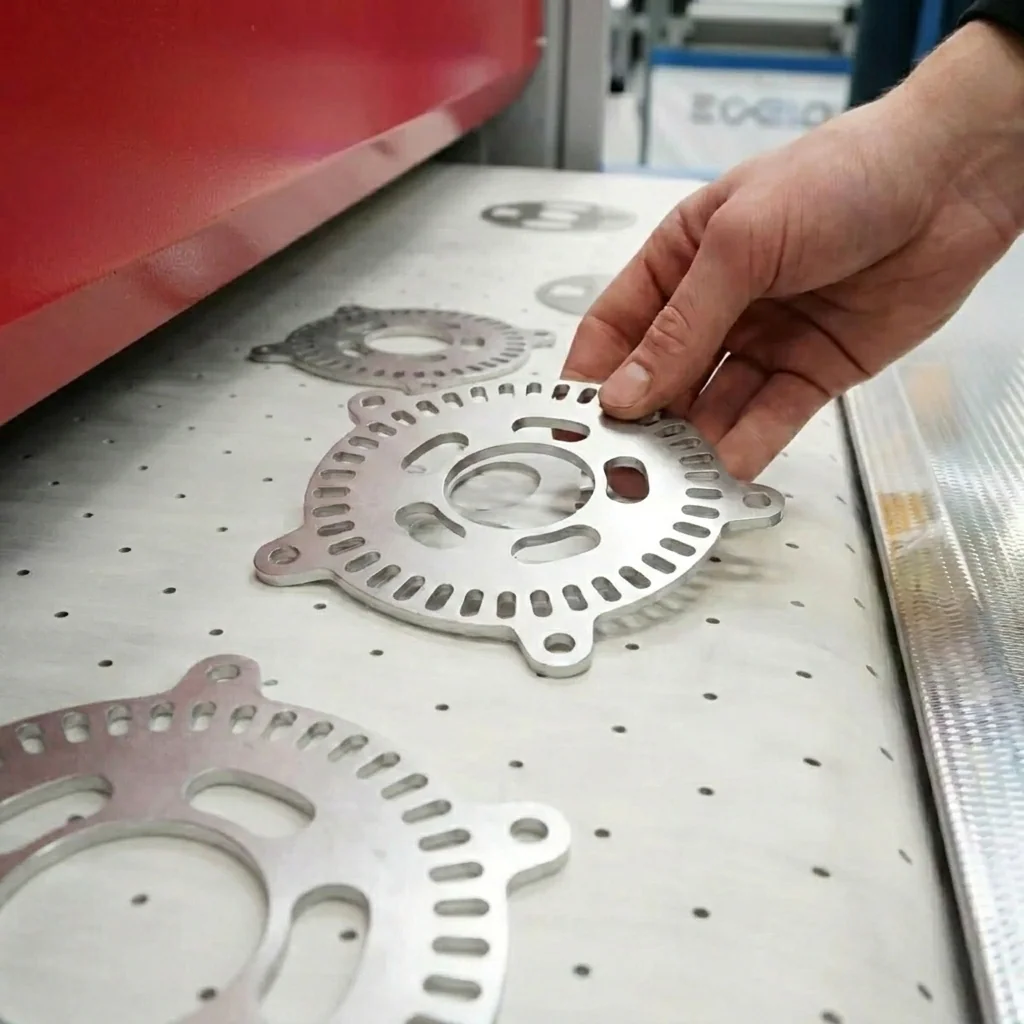
The Hans Weber 1350 is a modular, through-feed deburring and finishing machine with a 1350mm (53″) working width. Parts are placed on a magnetic vacuum conveyor belt and pass through a series of processing stations at controlled speed. Each station performs a specific operation — heavy deburr, edge round, or surface finish — and can be engaged or bypassed per job.
The machine uses an i-Touch controller with saved recipes, allowing us to recall exact settings (belt speed, brush pressure, grit selection) for repeat orders. This ensures part-to-part consistency across production runs of any size.
Processing Stations
Our Weber 1350 is configured with four modular processing stations. Each station can be engaged independently depending on the finish requirements of your parts:
Station D — Contact Roller
- Heavy deburring & slag removal
- Rubber-coated roller (25–60 Shore)
- Abrasive belt under contact pressure
- Pre-grinding for thick plate parts
Station P — Planetary Head
- Uniform all-around edge rounding
- Dual-rotation planetary brushes
- Inner & outer contours processed equally
- Patented overlapping tool paths
Station R2 — Multi-Rotation Brush
- Fine edge rounding on thin sheets
- Intermeshing brush pairs
- Safe for coated/foiled materials
- Consistent across full 1350mm width
Station SB — Scotch-Brite
- Non-woven abrasive finishing
- Directional or cross-hatch grain patterns
- Pre-paint surface preparation
- Cosmetic brushed-metal finish
Deburring
Deburring removes the raised material (burr) left on the bottom face of a part after laser cutting, plasma cutting, or punching. A burr forms when molten or sheared material re-solidifies on the exit side of the cut. If left in place, burrs cause:
- Assembly interference: Parts won't sit flat against mating surfaces
- Injury hazard: Sharp burrs cut hands during handling and installation
- Coating failure: Powder coat and paint cannot adhere reliably over a raised burr
- Dimensional error: Stacked parts with burrs introduce cumulative height error
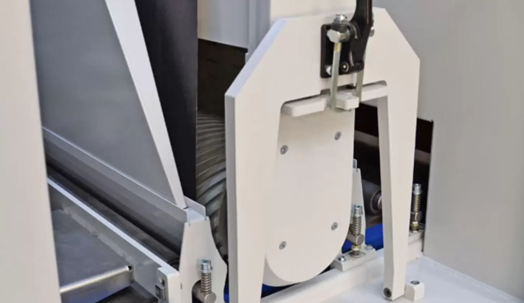
Our Contact Roller station (D) uses a coarse abrasive belt pressed against the part surface under controlled pressure. The belt removes the burr flush to the material surface without removing significant parent material.
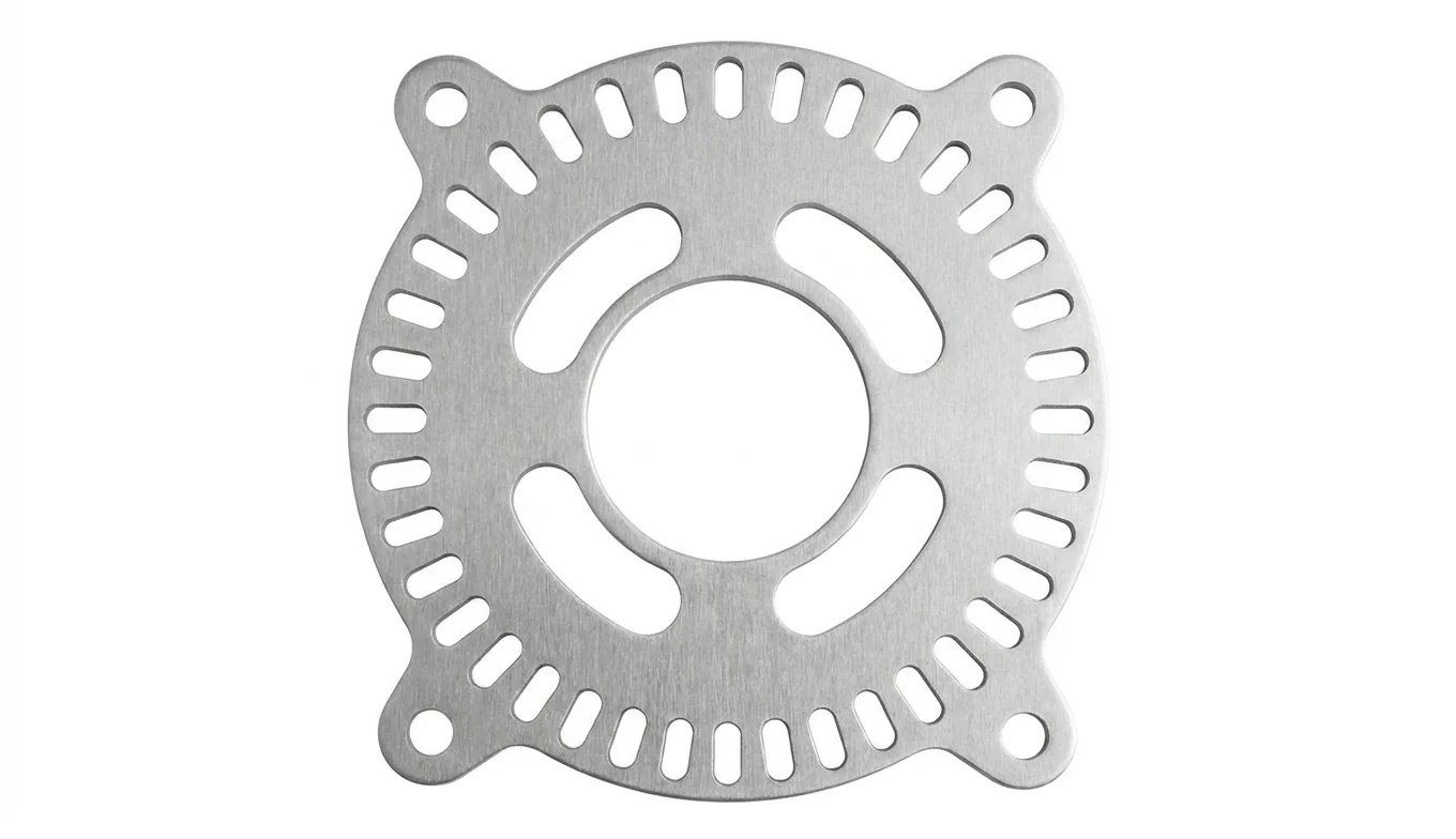
Before & After: Underside Deburring
The comparison below shows the underside of a laser-cut sheet metal part before and after processing through the Hans Weber 1350 Contact Roller station. Drag the slider left and right to compare.
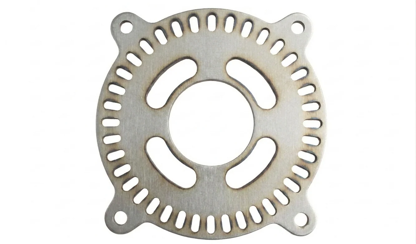
← Drag slider to compare →
Deburring vs Edge Rounding: Side Comparison
Both operations run in sequence on the Weber 1350. Drag the slider to see the visible difference between a deburred surface and one that has also received edge rounding treatment.
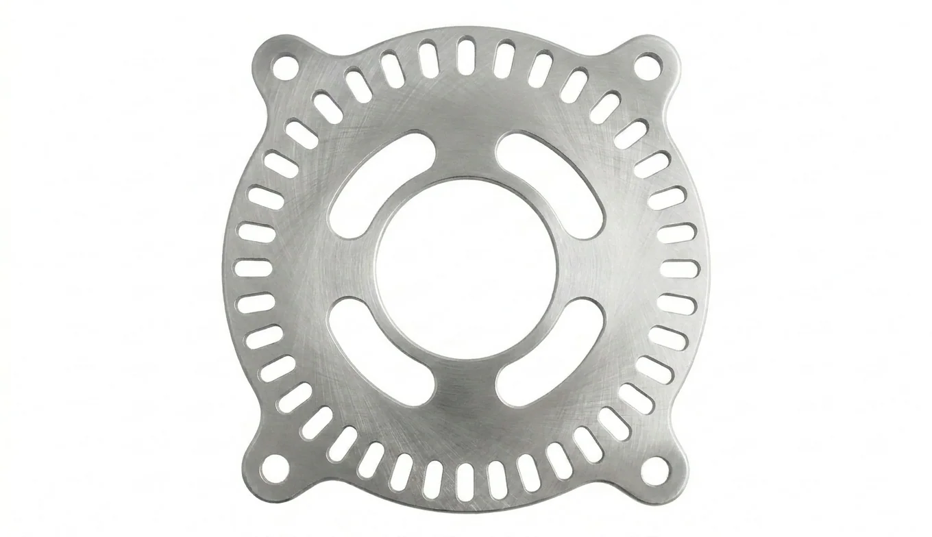
← Drag slider to compare →
Edge Rounding
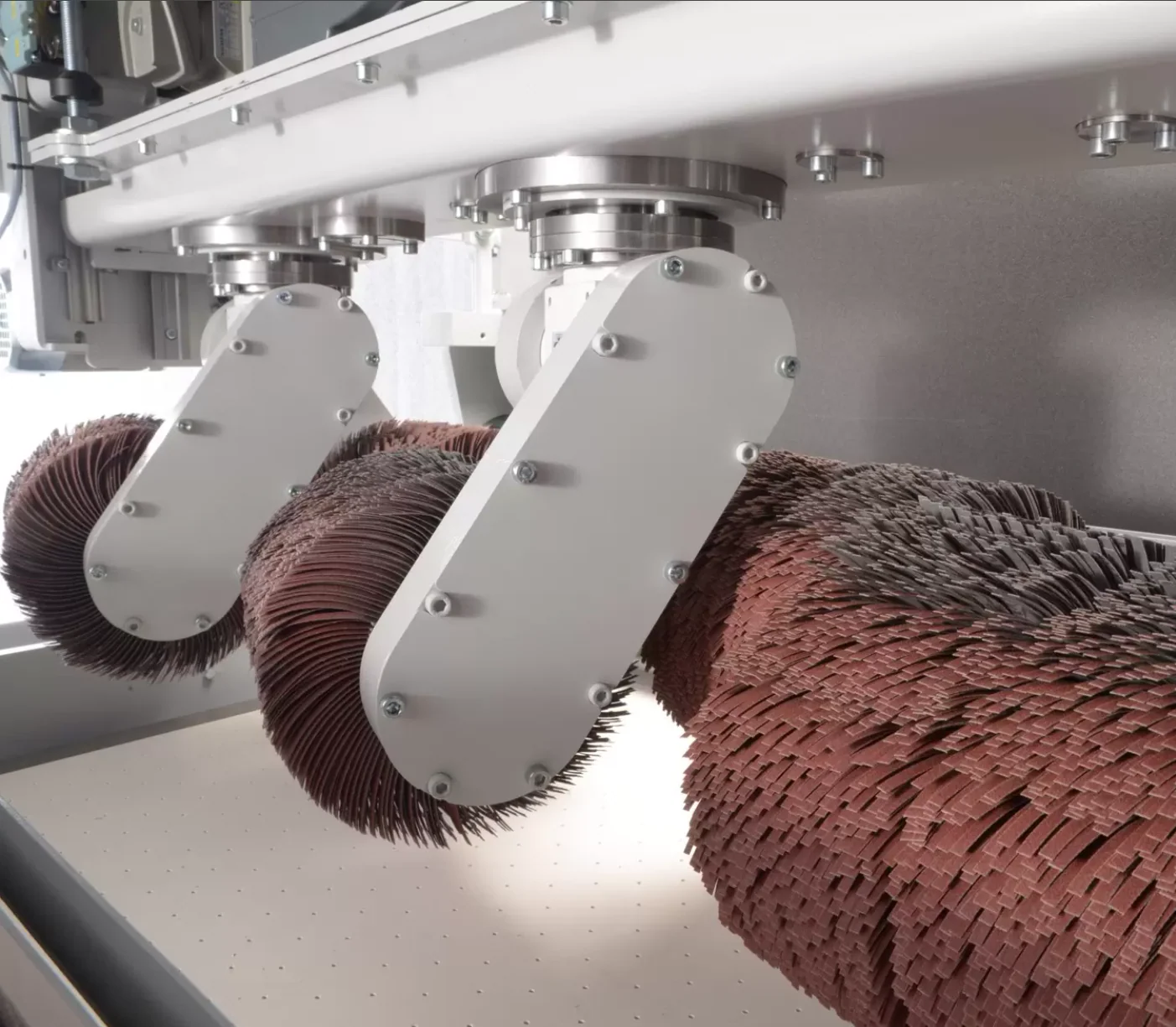
Edge rounding converts sharp, square-cut edges into a controlled radius. This is critical for:
- Safety Rounded edges eliminate cut hazards during handling and end-user contact
- Coating Powder coat and paint flow around a radius — they pull away from a sharp edge, leaving it unprotected
- Fatigue Sharp edges act as stress risers. Rounding improves fatigue life in cyclically loaded parts
- Aesthetics Rounded edges look and feel premium; sharp edges look unfinished
Edge radius options
| Radius Class | Approximate Radius | Best For |
|---|---|---|
| Light break | 0.2–0.5mm (0.008–0.020″) | General deburr + light rounding; functional parts |
| Standard round | 0.5–1.0mm (0.020–0.040″) | Powder coat prep; safety-critical edges |
| Heavy round (R2) | 1.0–2.0mm (0.040–0.080″) | Maximum coating adhesion; architectural/exposed parts |
Scotch-Brite Surface Finishing
The Scotch-Brite station uses non-woven abrasive wheels or belts to apply a uniform, directional grain pattern to the part surface. This operation serves two purposes:
- Surface preparation: Creates a consistent surface profile (anchor pattern) for paint, powder coat, or adhesive bonding
- Cosmetic finish: Produces a brushed-metal appearance similar to consumer electronics and architectural panels
Available grain patterns
| Pattern | Grit Range | Appearance |
|---|---|---|
| Coarse grain | 80–120 | Aggressive texture; industrial look; maximum adhesion profile |
| Medium grain | 150–220 | Balanced texture; standard pre-paint prep |
| Fine grain | 320–400 | Smooth satin finish; architectural/consumer cosmetic |
Oxide Removal
When mild steel is laser-cut with oxygen assist gas, the cut edges develop a dark oxide layer (burnt-orange to black discoloration). While this oxide can actually improve paint adhesion in some cases, it is often undesirable for:
- Welding: Oxide inclusions in a weld cause porosity and weaken the joint
- Tight-fit assemblies: The oxide layer adds 0.001–0.003″ to the edge, affecting slip-fit tolerances
- Cosmetic exposure: Visible edges on finished products look inconsistent with oxide
The Contact Roller station with a fine-grit belt removes oxide from cut edges in a single pass, leaving bright, clean steel ready for welding or finishing.
Part Size Limits
The Weber 1350 is a through-feed machine — parts ride on a conveyor belt through the processing stations. This imposes specific size constraints:
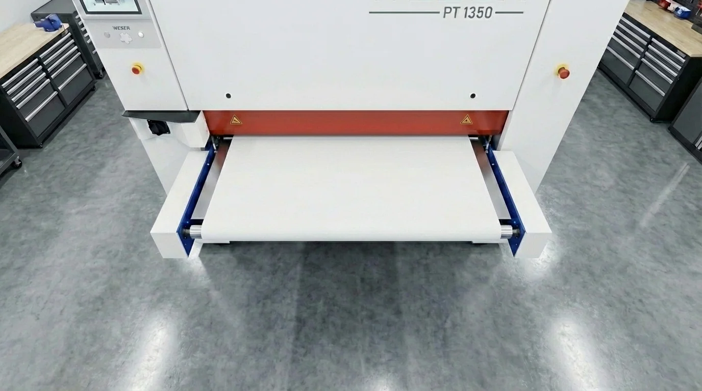
| Dimension | Limit | Notes |
|---|---|---|
| Maximum width | 1350mm (53″) | Parts wider than this cannot pass through the machine |
| Maximum length | Unlimited | Through-feed system; any length supported by conveyor |
| Minimum part size | 50 × 50mm (2″ × 2″) | Smaller parts may shift or flip under brush pressure |
| Minimum thickness | 0.5mm (0.020″) | Thinner material may deform under contact roller pressure |
| Maximum thickness | 100mm (3.94″) | Limited by machine clearance and brush travel |
For a checker that tests a blank against every one of these limits at once — and against the material, since not everything we stock can be deburred — see deburring size limits.
Weight limits
The magnetic/vacuum conveyor holds parts in place during processing. Very heavy plate parts (over 25kg) may require reduced belt speed to ensure adequate hold-down force. Extremely lightweight thin parts (< 0.5mm) may need vacuum assist rather than magnetic hold.
Design Guidelines for Deburring
Designing with the Weber 1350 in mind ensures your parts process cleanly and arrive with the finish you expect:
1. Avoid very narrow slots and fingers
Slots narrower than 3mm (0.125″) and fingers/tabs narrower than 5mm are at risk of catching on rotating brushes. If your design requires thin features, note them on your order so we can adjust brush pressure or bypass those features.
2. Minimum part size: 50 × 50mm
Parts below this threshold cannot be reliably held by the conveyor during processing. For small parts, we offer hand-deburring as an alternative — add a note to your order.
3. Specify which side to process
The Weber processes the top face of the part as it passes through. If both sides need deburring or finishing, specify "both sides" so we run two passes. For parts with a cosmetic face and a hidden face, tell us which is which.
4. Bend-formed parts cannot be processed
The Weber only processes flat parts. If your part has bends, deburring and edge rounding must be completed before the bending operation. Our standard workflow handles this automatically — deburr first, bend second.
5. Edge rounding affects edge-to-feature dimensions
A 1mm edge round removes approximately 0.7mm of material at the edge. If you have features (holes, slots) very close to the part perimeter, the rounding operation may encroach on them. Maintain at least 2× the specified edge radius between any feature edge and the part perimeter.