A through-feed line has a window, and it is not the same window as the laser.
The Weber 1350 is named for its 1350 mm belt, but the widest part we run through it is 48″. Length is effectively unlimited, so only the narrow dimension has to clear it. The floor is 2″ × 2″ — eight times the laser’s minimum — and it only takes flat, bare stock. Enter a blank below and it checks all of it, material included.
The two ends of the Weber’s window, drawn to scale against each other. Width is the only bounded dimension — the line is through-feed, so length is limited by what the laser can cut, not by the deburrer.
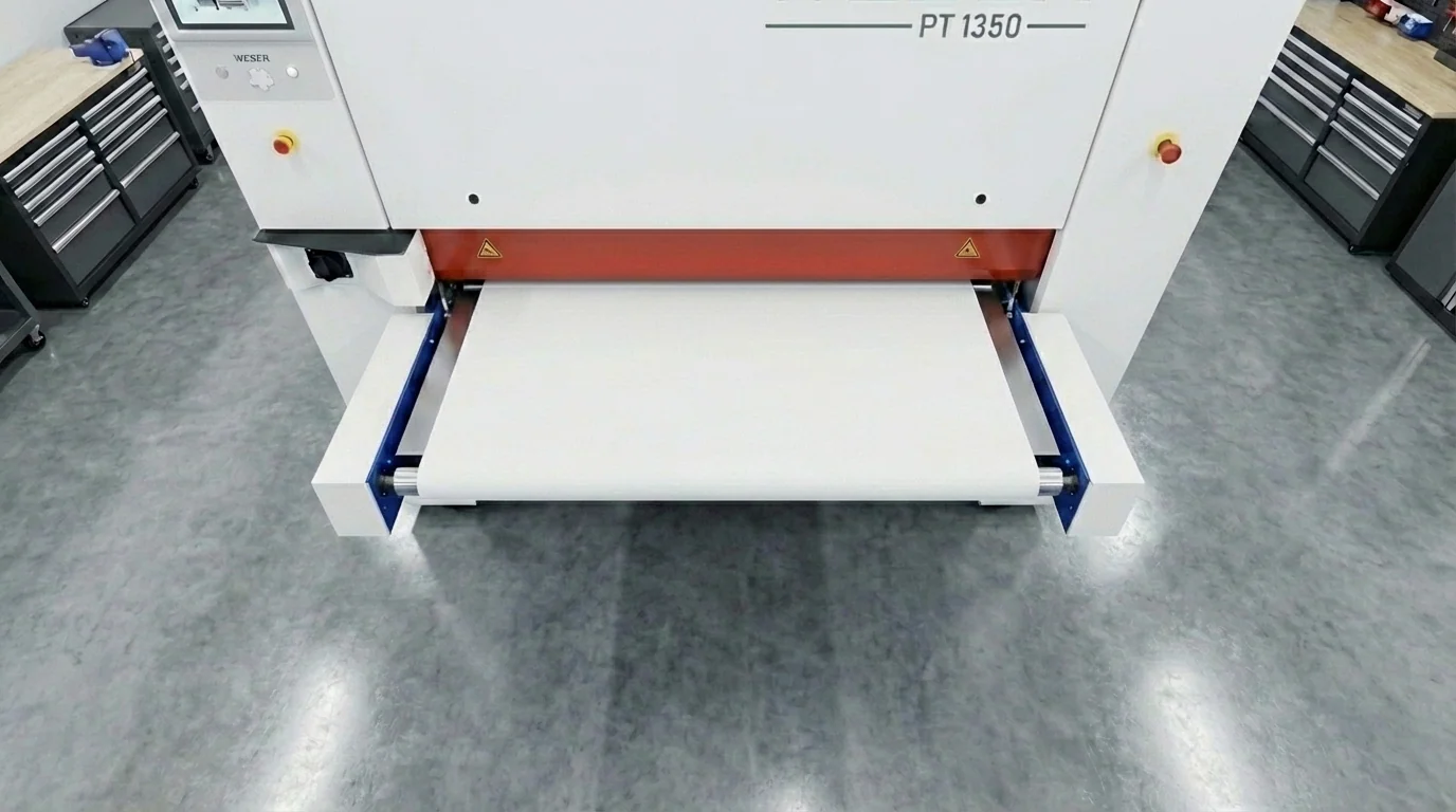
Everything about the Weber follows from it being a through-feed machine: parts ride a conveyor under fixed brush heads. Width is bounded by the belt, length is not bounded at all, and the part has to be big and stiff enough for the belt to hold onto.
The belt is the constraint you can see. Parts feed long-edge-first, so a 60″ × 12″ panel passes comfortably while a 58″ × 70″ one cannot pass at all.
Two machines, two windows. Where they disagree is where a part comes back hand-finished, or comes back with an as-cut edge you were not expecting.
The laser will give you a blank up to 119″ × 59″. The deburring line stops at 48″ wide. That leaves an 11″ band — parts between 48″ and 59″ on their narrow dimension — that we can cut but cannot machine deburr. Those get hand finished, which is slower and does not give the same uniform edge round.
It runs the other way at the small end, and by a much bigger factor. The laser will cut down to 0.250″ square; the Weber needs 2″ square. That is an 8× difference, and it is the one that catches people out on small brackets and shims — perfectly cuttable, not machine-deburrable.
Neither is a dead end. Small parts get hand deburred, fixtured on a carrier plate, or cut as a tabbed gang sheet and separated after finishing. Wide parts get hand finished. But both cost more than letting the machine do it, so it is worth knowing at design time. See the full cut window on minimum & maximum part sizes.
That phrase is the whole policy. An abrasive line takes the top off whatever it touches, so anything specified for its surface — or already coated — does not belong on it. Every gauge below is also checked against the thickness window.
The machine is forgiving about most geometry and unforgiving about four specific things. All four are cheap to fix in CAD and expensive to discover in production.
3 mm and fingers or tabs narrower than 5 mm can catch a rotating brush and get bent or torn. If the design needs them, flag it on the order and brush pressure gets dialled back or those features bypassed. This is a different limit from the laser's minimum slot width, which is 1.5× thickness.1 mm edge round removes roughly 0.7 mm of material at the edge. A hole or slot sitting right against the perimeter will get encroached on and end up open to the edge. Keep at least 2× the specified edge radius between any feature and the part perimeter.What comes up most about what the Weber will and will not take.
2″ × 2″ (50 × 50 mm). Below that the brushes can grab the part and eject it, because the conveyor cannot hold it. Smaller parts are still fine to order — they are hand deburred, fixtured on a carrier plate, or cut as a tabbed gang sheet and snapped apart after finishing. Note this floor is 8× the laser's minimum part size, so plenty of parts can be cut but not machine deburred.48″ wide. The belt itself is 1350 mm (about 53″) — that is what the machine is named for — but 48″ is the widest part we run, across every material. Length is effectively unlimited because it is a through-feed conveyor, so only the narrow dimension has to clear it. A 60″ × 12″ panel runs comfortably; a 58″ × 70″ one cannot pass at all.59″ wide; the deburring line takes 48″. That 11″ band gets hand finished instead. The gap is far bigger at the small end — 0.250″ minimum on the laser against 2″ on the Weber. Check both windows on minimum & maximum part sizes.0.020″ to 3.94″ (0.5 to 100 mm). Below the floor the material deforms under contact-roller pressure; above the ceiling it exceeds machine clearance. Every sheet gauge we stock is inside that window except spring steel, which we only hold at 0.005″ — far too thin to run.Corten and weathering steel is excluded — it is specified for the patina it develops, and an abrasive line strips the surface that patina forms on. Pre-weathered or heavily rusted material, painted parts, and previously powder-coated parts are excluded for the same reason. Galvanized and electro-galvanized stock and MIC-6 cast plate need confirming: the brush cuts through zinc right where it is protecting, and MIC-6 arrives machined flat to ±0.005″ which an abrasive line will undo. The table above marks each one.1 mm edge round removes about 0.7 mm of material at the edge, so a hole or slot close to the perimeter may get encroached on and break through to the edge. Keep at least 2× the specified edge radius between any feature and the perimeter.0.125″ (3 mm) and fingers or tabs under 5 mm can catch on the rotating brushes. Flag them on the order — brush pressure can be adjusted or those features bypassed. Note this is a different limit from the laser's minimum slot width of 1.5× thickness.25 kg the belt speed is reduced to keep enough hold-down force, which just means the part takes longer. Very thin, very light parts go the other way and may need vacuum rather than magnetic hold. Neither blocks the job. Quote codes 3401–3406 in the DFM lookup cover the hard size and weight rejections.