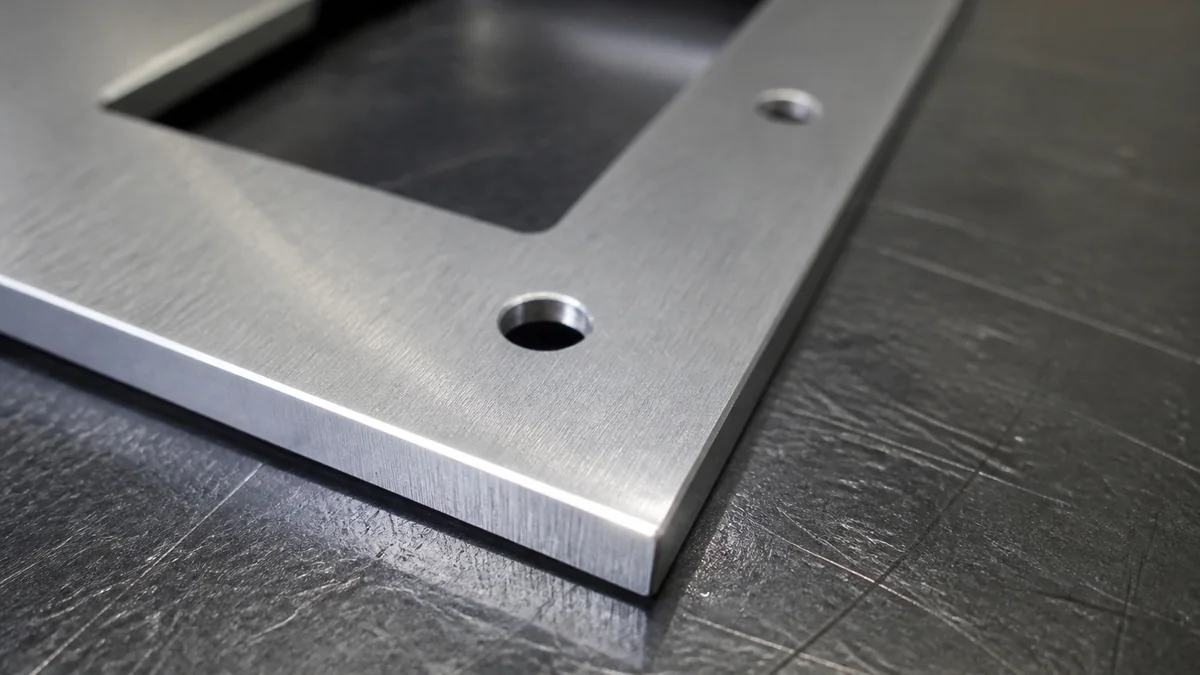
Round the outline. Break the edge.
On any part a person will pick up, fillet the outside corners in CAD and order an edge break on the cut thickness. The first reason is safety. Coating wrap and a finished feel come along with it.
The laser does not leave a friendly edge. It leaves a square cut. If the outline also meets at 90°, you have designed a point. Gloves do not save you from that combination — they just delay the cut until the next person in the chain.
Fillet every outside corner people can grab. Floor at 0.030″. One times thickness is the comfortable default on panels, doors, and covers.
A standard round on the Hans Weber 1350 takes the knife off the top and bottom of the sheet. Do not model this as a chamfer on the edge face.
A radiused outline with a square knife edge still cuts. A broken edge with a needle corner still stabs. Specify both, or the leftover sharpness does the injury.
The hazard is the point, not the burr.
People blame “the burr.” The burr is only half of it. A clean nitrogen-cut stainless edge with no dross is still a blade. A 90° outside corner turns that blade into something that finds skin.
Cuts happen in the places drawings never mention: the receiving dock, the kit cart, the assembler lining up the first PEM, the electrician fishing a panel into a rack. Product-facing covers and machine guards add the end user. A drawing that says nothing about edges is silently specifying a razor.
This is not a cosmetic preference dressed up as safety. A knife-edge panel will cut through a nitrile glove. Blood on a powder-coated cover is a rejected part and an injury report. Breaking the corner in CAD costs nothing. Leaving it sharp costs both.
Do not swap the two specs.
Corner rounding lives in the flat pattern. Edge break lives on the cut thickness. They solve different cuts, and one does not replace the other.
Internal corners are a different question. The laser already leaves a small radius in a notch, near half the kerf. You do not need a large fillet there for safety. Save the CAD radius for outside corners, tabs people pinch, and cover plates with exposed points.
By alloy family and thickness.
Use the picker for the gauge you are ordering, then read the two numbers: the outside-corner radius to model, and the edge-break class to order.
Recommended edge break & corner radius
Outside-corner radius to model
Floor is 0.030″ on every handled part. Below that, the corner still feels like a point. Stainless at the thin end steps up because a nitrogen-cut, work-hardened edge stays sharper than aluminum of the same gauge.
| Thickness | Aluminum | Mild steel | Stainless |
|---|---|---|---|
| 0.024–0.040″ | R 0.030″ | R 0.030″ | R 0.040″ |
| 0.048–0.075″ | R 0.040″ | R 0.040″ | R 0.060″ |
| 0.080–0.125″ | R 0.060″ | R 0.060″ | R 0.060″ |
| 0.135–0.188″ | R 0.090″ | R 0.090″ | R 0.090″ |
| 0.250″ and thicker | R 0.125″ | R 0.125″ | R 0.125″ |
A compact rule if you do not want the table in your head: R ≥ max(0.030″, 0.5T). Use 1T on doors, covers, and anything an installer will carry by a corner.
Edge break on the cut thickness
These match the radius classes already published on the deburring guide. Thin stock gets a light pass so the Weber does not dish the sheet. Powder-coated or heavily handled plate steps up so coating wraps the edge.
| Thickness | Aluminum | Mild steel | Stainless | Class |
|---|---|---|---|---|
| Up to 0.040″ | 0.008–0.015″ | 0.010–0.020″ | 0.010–0.020″ | Light break |
| 0.048–0.125″ | 0.020–0.040″ | 0.020–0.040″ | 0.020–0.040″ | Standard round |
| 0.135″ and up | 0.030–0.060″ | 0.040–0.080″ | 0.030–0.060″ | Standard to heavy |
Fillet the outline. Note the edge.
The laser cannot cut a chamfer through the thickness. If you model one on the edge face, DFM will strip it or flag it. Put the safety radius where the laser can actually cut it.
Weber first, then the brake.
Edge rounding runs on the Hans Weber 1350 while the part is still flat. Formed parts do not go through the brushes. Deburr, then bend. That sequence is already the shop default.
The machine combines a wide belt with multi-rotation brushes, 53″ wide. It takes the knife off the cut, rounds the edge to the class you ordered, and can lay a grain for powder or anodize. Parts smaller than about 2″ × 2″ need a carrier or a hand pass. Parts thinner than 0.020″ can dish under the head — that is why the thin-gauge row in the table is a light break.
If you only needed the burr gone, a light pass is enough for function. If a person will hold the part, order the standard round and put the CAD radius on the outline. The two operations are cheap compared with a cut.
The Weber only processes flats. Hardware, powder, and anodize come after forming. Details are on the metal finishing page.
Every material page lists Weber capability for that alloy. Use this guide for the radius to ask for.
Safety first. The edge also lasts longer.
The reason to design the break in is still a hand. Powder wrap, anodize integrity, and fatigue life are what you get for free once the knife is gone.
Powder pulls off a sharp edge. The film is thinnest at the corner, and that is where it chips in the field. A standard round plus R 0.030″ on the outline is the minimum that lets the coating turn the corner. Anodize has the same failure on a knife edge: the oxide thins, dyes burn through, and the corner looks raw.
A sharp corner is also a stress riser. On a cyclically loaded bracket the crack starts at the point you left in the DXF. Rounding the outline is fatigue insurance that costs a few extra millimeters of laser path.
Six lines before you upload.
If the part will be unpacked, assembled, or installed by a person, every box should already be true.
Upload the file with the outline radii already in it.
Fillet the outside corners, pick the material and thickness, and note standard edge rounding if the part is handled or coated. We cut the radius and break the knife before the part is bent.
Upload your design →