STATE / 01
Functional prototype
Test assembly, ergonomics, load paths, clips, fasteners, clearances, and service access in a documented material.
One design / rapid feedback
Real hardware interfaces
Revise the file, not the tool
A prototype should do more than occupy space. It should reveal how the product carries load, accepts hardware, survives assembly, and moves through the physical world.

A rendering can prove that a product looks coherent. A physical prototype must prove that the product behaves coherently.
Does the latch flex without breaking? Can a technician reach the fastener? Will the connector clear the wall? Does the enclosure resist the load at the mounting boss? Can two parts be assembled without forcing them past each other? These are not visual questions. They are questions for matter.
Too many prototypes answer only one: is the shape approximately right? They are printed quickly in a process chosen for convenience, inspected briefly, and discarded before the material has revealed anything meaningful. The team then changes processes, changes materials, changes tolerances, and discovers the real behavior after the design is supposedly finished.
Rapid manufacturing becomes valuable when each iteration preserves more of the final system: the wall stiffness, snap behavior, threaded interfaces, chemical environment, assembly clearance, and geometry that will exist in use.
HP Multi Jet Fusion builds parts in Nylon PA 12: a dense engineering thermoplastic with balanced strength, useful ductility, chemical resistance, and a long history in functional polymer components.
HP reports 48 MPa tensile strength across XYZ directions and a tensile modulus of roughly 1,700–1,800 MPa for its High Reusability PA 12. That balance matters. A prototype bracket or enclosure should not be strong only when the load happens to align with the easiest build direction.
Production-grade does not mean identical to every production process. MJF PA 12 is not metal, and a printed part is not automatically equivalent to an injection-molded part. Surface, process history, geometry, moisture, temperature, wall thickness, and test method all matter. The claim is narrower and more useful: this is a documented engineering material capable of producing functional parts, not merely visual stand-ins.
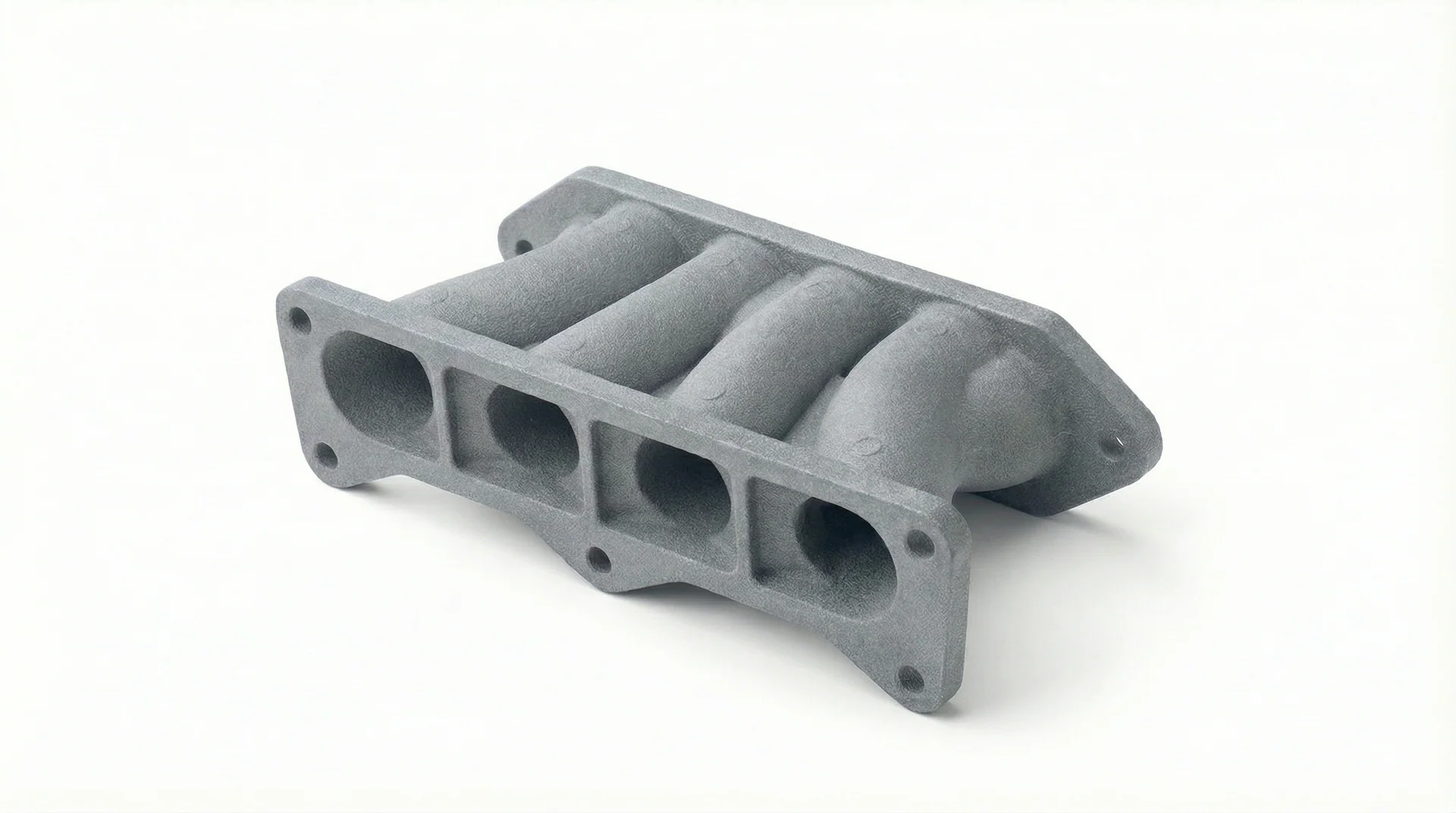
Multi Jet Fusion combines powder spreading, precisely placed agents, controlled energy, and cooling into a repeatable layer-by-layer manufacturing system.
The loose powder supports the part throughout the build. That removes the sacrificial support structures common to many extrusion and resin processes and makes undercuts, nested geometry, internal channels, and dense three-dimensional packing possible.
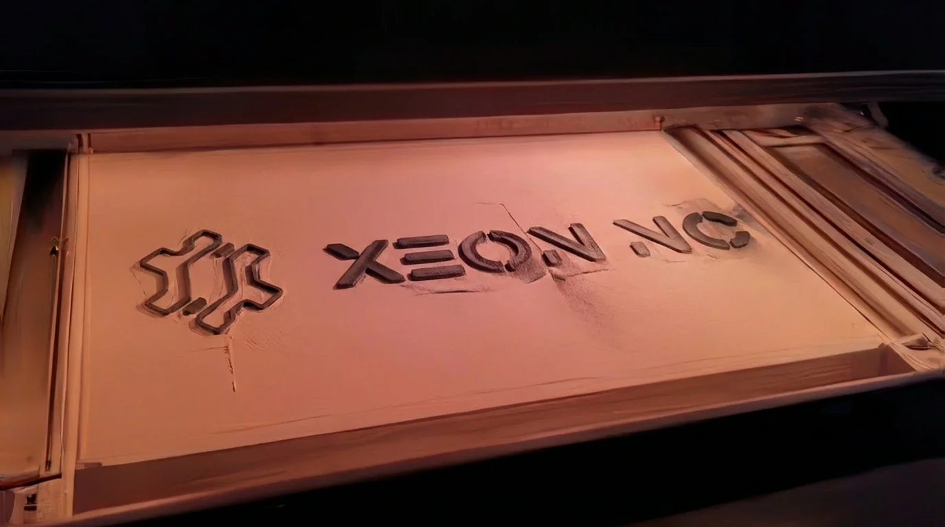
The same process can manufacture the first fit-check part, the units that bridge a tooling delay, and the final low-volume production component.
Test assembly, ergonomics, load paths, clips, fasteners, clearances, and service access in a documented material.
Ship pilot units, field trials, or early customer hardware while long-lead molds or supply chains are still being established.
Keep complex or low-volume polymer components additive when tooling economics never become the better system.
The advantage is not that every product should remain printed forever. It is that the organization can choose the right transition point. Tool when volume, surface, resin, and unit economics justify it. Stay additive when variation, complexity, speed, or low volume remains more valuable.
MJF is strongest when geometry is doing work: locating, protecting, routing, joining, supporting, or moving.
Ribbed walls, cable routes, mounting bosses, vents, labels, and complex internal packaging in one part.
Inspection nests, assembly aids, drill guides, soft jaws, locating tools, and ergonomic factory hardware.
Lightweight supports with ribs, fillets, captured nuts, and load paths that would be expensive to machine.
Functional retention geometry for validating insertion force, service access, and repeated assembly behavior.
Internal passages and compact routing geometry, with sealing or post-processing when fluid performance requires it.
Interlocking or moving components that consolidate part count when clearances and powder-removal paths are intentional.
MJF removes support structures and dedicated tooling. It does not remove material behavior, heat, resolution, or the need to recover powder from the geometry.
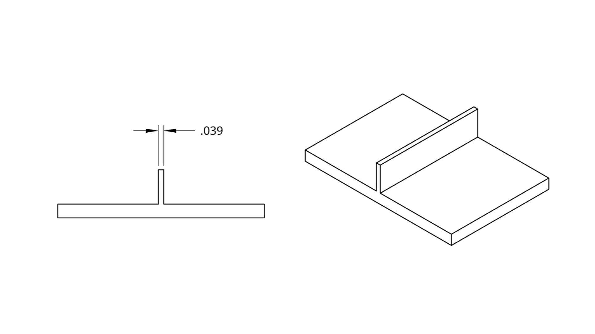
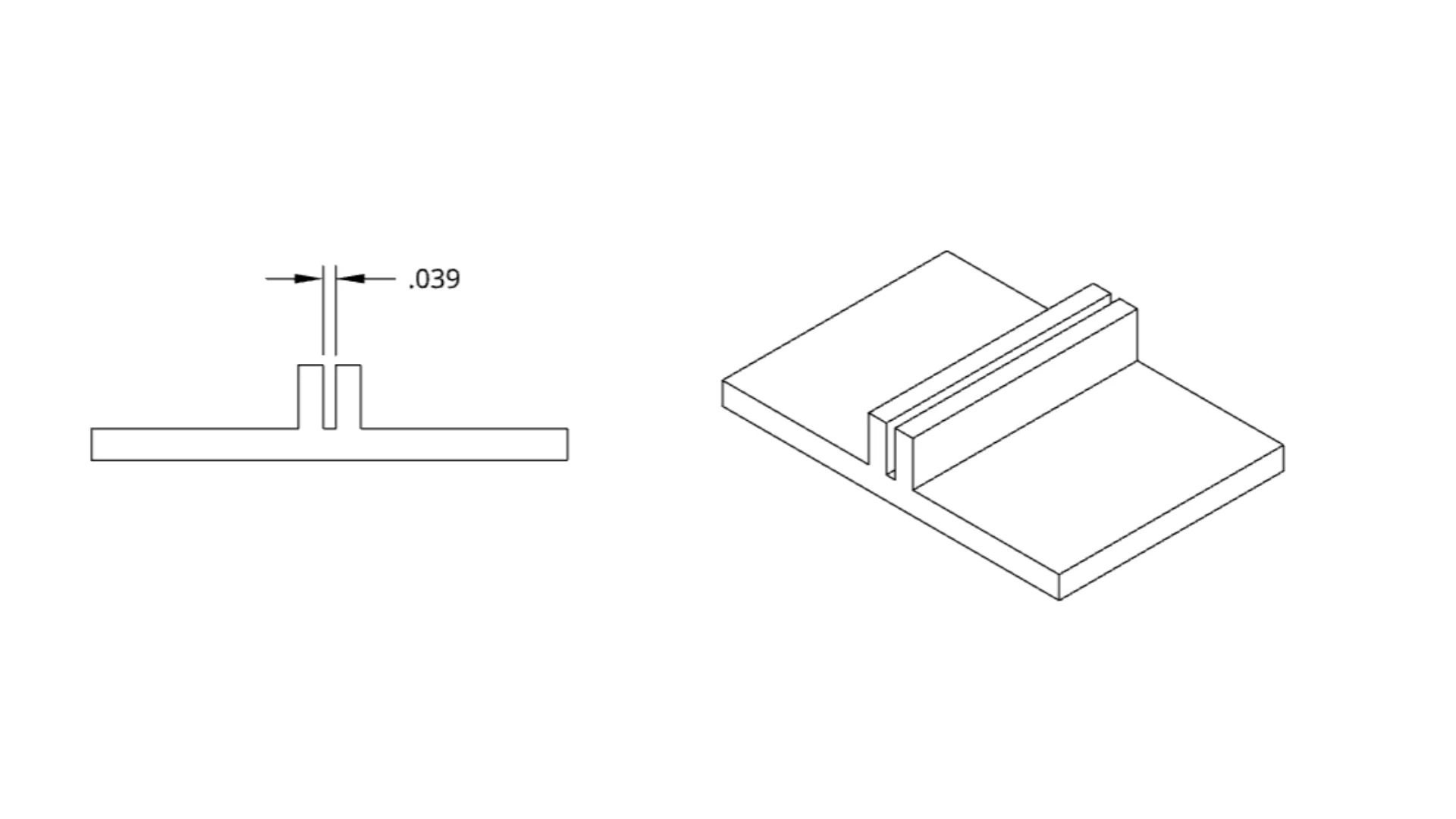
The mature additive decision is not “can this be printed?” It is “is printing the best production system for this requirement?”
Hybrid manufacturing is often the answer. Print the geometry that benefits from additive complexity. Use laser-cut or bent metal for stiffness and shielding. Add heat-set inserts for repeated fastening. Post-machine only the surfaces that need tighter control. A useful manufacturing platform composes processes instead of forcing every requirement through one machine.
When functional parts can move from file to matter without a dedicated tool, small teams can test more ideas and large teams can take more uncertainty out of production.
The first prototype does not have to be a disposable model. It can be the first physical state of the product: made in an engineering material, carrying real hardware, exposing real clearances, and generating information that survives into the next revision.
That changes the economics of learning. A new revision is not a new mold. A low-volume SKU is not a tooling crisis. A replacement fixture is not a sourcing project. Geometry becomes an operational asset that can be revised, stored, and produced when the physical system needs it.
Upload a STEP or STL model for HP MJF Nylon PA 12. Prototype one part, bridge a production gap, or manufacture the geometry as the final component.
Upload your model →