01 / Neutral
Vendor-independentMoves product geometry between CAD, CAM, CAE, and inspection systems.
What the format contains, why manufacturing uses it, and how to export a model that survives the handoff.
Moves product geometry between CAD, CAM, CAE, and inspection systems.
Preserves connected faces, edges, curves, holes, radii, and topology.
Can carry assemblies, colors, names, validation properties, and PMI.
Ideal for formed sheet metal, CNC machining, DFM, CAM, and inspection.
STEP is a vendor-neutral way to move structured product data between engineering and manufacturing systems.
STEP stands for STandard for the Exchange of Product model data. It belongs to the ISO 10303 family of standards. You will commonly see the filename extensions .step, .stp, and sometimes .p21.
A native CAD file is written for one design system. A STEP file is written for exchange. It gives different software a shared representation of the part so a model created in one CAD package can be opened by another CAD package, CAM system, manufacturability checker, or inspection application.
The everyday phrase STEP file usually refers to an ISO 10303-21 physical exchange file, also called a Part 21 file. The standard is much larger than the familiar file extension: it defines data models, implementation methods, and application protocols for different kinds of product information.
At its core, STEP can describe precise geometry and the relationships that turn individual surfaces into an actual part.
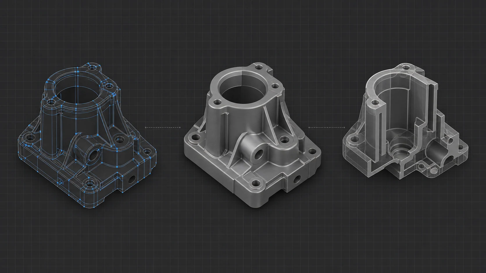
Solids, shells, surfaces, curves, faces, edges, vertices, holes, fillets, chamfers, and freeform spline geometry.
Parts, component instances, placements, assembly relationships, names, and product structure when the selected protocol and software support them.
Colors, layers, visibility, and other presentation data can survive in capable AP214 and AP242 workflows.
AP242 can carry semantic or graphical dimensions, tolerances, GD&T, annotations, and validation properties when both ends implement them.
Most STEP files are readable ASCII text organized into a header and a data section.
ISO-10303-21;
HEADER;
FILE_DESCRIPTION(('STEP AP242'),'2;1');
FILE_NAME('bracket_rev_b.step','2026-08-25T18:00:00Z',(''),(''),'CAD exporter','CAD system','');
FILE_SCHEMA(('AP242_MANAGED_MODEL_BASED_3D_ENGINEERING_MIM_LF'));
ENDSEC;
DATA;
#10 = ADVANCED_BREP_SHAPE_REPRESENTATION(...);
#11 = MANIFOLD_SOLID_BREP(...);
#12 = CLOSED_SHELL(...);
/* thousands of linked product and geometry entities */
ENDSEC;
END-ISO-10303-21;
The HEADER identifies the file, timestamp, originating system, and schema. The DATA section contains numbered entities. Those entities reference one another to build up coordinate systems, products, surfaces, edge loops, shells, solids, assemblies, presentation data, and PMI.
This graph of linked entities is why a STEP file can represent far more than a collection of triangles. It can preserve that a round hole is bounded by a cylindrical surface, that two faces share an edge, and that multiple bodies are placed within an assembly.
The application protocol tells software which product-data model the file uses.
Widely supported for configuration-controlled mechanical design and basic geometry. It remains useful when older systems require it, but it carries less presentation and model-based definition capability than newer options.
Legacy compatibilityCommon in automotive and general mechanical exchange. It improved support for colors, layers, assemblies, and related product data and is still a practical compatibility choice.
Broad compatibilityThe current direction for managed model-based engineering. It combines and advances capabilities associated with AP203 and AP214, including stronger support for PMI and long-term product-data workflows.
Preferred when supportedOur practical recommendation: choose AP242 when the sending and receiving systems support it. Use AP214 when an established downstream workflow asks for it. Use AP203 only when compatibility with a legacy system requires it.
The latest AP242 standard is ISO 10303-242:2025, edition 4. Your CAD export dialog may present an earlier AP242 edition or use a shorter label. Interoperability depends on the specific exporter and importer, not just the name shown in the menu.
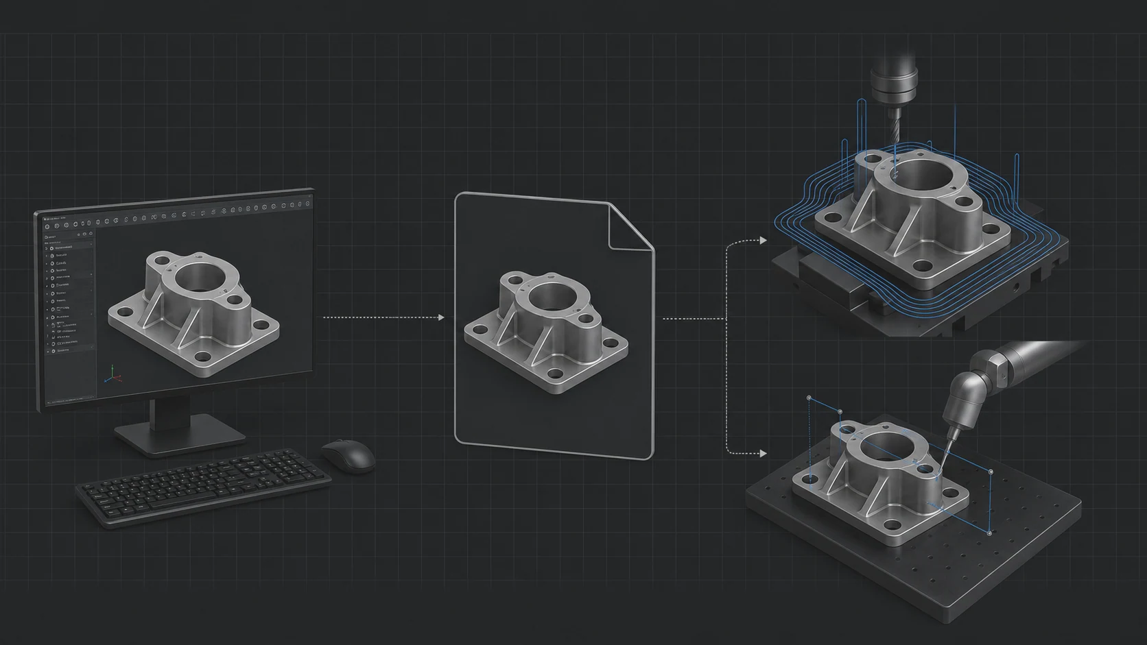
A precise 3D solid gives manufacturing software more geometry to evaluate and less geometry to reconstruct.
The finished solid can expose thickness, planar faces, cylindrical bend surfaces, bend radii, holes, and flange relationships. A capable system can use that geometry to recognize a formed sheet-metal part, test whether it can unfold, and run manufacturability checks. The model still does not replace material selection, grain direction, bend allowance, K-factor, or special bend notes.
Pockets have depth. Holes have axes. Curved faces have exact surface definitions. CAM software can build toolpaths from this geometry without asking a programmer to rebuild a three-dimensional part from orthographic views or disconnected profiles.
STEP can communicate component placement and product structure, and AP242 can carry PMI for model-based definition. Inspection and metrology software can compare measurements against the same nominal geometry used to plan manufacturing.
No file format is best for every job. The right handoff matches the manufacturing process.
The best export is not the one with the most options selected. It is the smallest complete model that clearly controls the part.
For an Onshape-specific walkthrough, see our sheet-metal STEP export guide.
STEP is robust, but a successful save does not guarantee a successful manufacturing handoff.
Units can be encoded, but importer defaults and bad export settings still cause inch-to-millimeter errors. Measure a known feature after reopening.
Tiny gaps, sliver faces, self-intersections, and translation tolerances can turn a solid into a surface set that requires healing.
The wrong configuration, hidden bodies, construction geometry, or an entire surrounding assembly may be exported by mistake.
Threads, tolerances, material, finishes, bend data, and critical requirements may not transfer unless they are encoded and supported.
An AP242 file can contain information that an older importer ignores. A familiar AP name does not guarantee equal implementation.
The imported shape may be precise yet lack sketches, constraints, dimensions, mates, and the chronological feature tree from the source CAD system.
B-rep gives software a mathematically precise boundary of the part. Feature recognition turns that boundary into manufacturing meaning.
B-rep means boundary representation. Instead of describing a part as a cloud of points or a skin made from triangles, a B-rep model defines the boundary between solid material and empty space using two connected layers of information:
Planes, cylinders, cones, tori, lines, circles, arcs, and spline surfaces define where each surface or curve exists in three-dimensional space.
Vertices bound edges, edges form loops, loops trim faces, faces join into shells, and closed shells enclose solid bodies.
Face and edge directions help the system determine which side is material, which side is empty space, and whether the boundary closes correctly.
The model records which faces share an edge and how surfaces meet. Those relationships are essential for recognizing holes, bends, pockets, flanges, and other features.
For example, a cylindrical surface by itself is only a cylinder. When that cylinder is bounded by circular edge loops, opens through two surrounding faces, and points into the solid, it can be interpreted as a through hole. A cylindrical face joining two planar sheet faces may instead be a bend. The same surface type can mean different things; topology provides the context.
When a STEP file enters the quoting system, we do not price the file extension. We evaluate the body, interpret manufacturing features, compare them with real process capabilities, and build a proposed manufacturing plan.
Read units and orientation, count bodies, check the bounding size, and verify that faces form usable closed geometry.
Determine whether the body behaves like uniform-thickness sheet metal, a machined solid, or another supported manufacturing process.
Group faces and edges into bends, flanges, holes, slots, pockets, bosses, chamfers, radii, patterns, and cut profiles.
Apply material, machine, tooling, access, collision, minimum-feature, and process rules to the recognized geometry.
Combine material demand, operations, setup, cycle time, finishing, quantity, risk, and customer requirements.
Uniformly separated face pairs help identify material thickness. Planar regions become candidate flanges. Cylindrical surfaces between those regions reveal bend location, inside radius, angle, direction, and the faces connected by the bend. Boundary loops identify the outside profile and internal cutouts.
Once the formed body is recognized, the system can create a manufacturing interpretation of the part:
Those results help estimate material usage, cutting time, bend operations, setup and handling time, tooling feasibility, and manufacturing risk. The production bend program is still validated against the actual material lot, machine, tooling library, tolerances, and shop requirements.
For a machined component, B-rep exposes the exact size and relationship of planar, cylindrical, conical, and freeform surfaces. Adjacency lets the system group those surfaces into candidate holes, counterbores, pockets, steps, bosses, slots, chamfers, fillets, and outside profiles.
That feature map supports quoting and process simulation by helping us estimate stock size, removed volume, drilling and milling operations, tool-diameter limits, depth-to-width ratios, setup orientations, tool changes, and likely cycle time. Tool and holder access can be evaluated against nearby walls and features, while simulated motion can reveal reach or collision problems before the part reaches a machine.
That is why STEP is so valuable to automated manufacturing. B-rep gives the system a precise, computable object. Feature recognition converts that object into operations. Simulation tests those operations against the factory. The quote prices the resulting plan—while ambiguous or high-risk conditions remain visible for human review.
For a deeper look at this connected workflow, read CAD Feature Recognition: The Future of Manufacturing.
Yes. They are common filename extensions for the same ISO 10303 Part 21 exchange format. The shorter .stp extension became common on systems that historically limited extensions to three characters.
Usually. Most CAD systems can import and modify the geometry with direct-modeling or feature-recognition tools. The original sketches, constraints, design dimensions, and feature history generally do not transfer as native editable features.
STEP can encode units and coordinate systems. Always verify by reopening the export and measuring a known dimension because incorrect settings and importer behavior can still create scale errors.
Yes. STEP can represent products, component instances, placements, and assembly relationships. Whether the receiving system preserves names, colors, hierarchy, and metadata depends on the protocol and implementation.
Use AP242 when both systems support it. AP214 remains a strong compatibility option for established workflows. Use AP203 when a legacy receiving system specifically requires it.
For precision manufacturing and CAD exchange, usually yes. STEP can preserve exact analytic and spline geometry plus topology. STL approximates the surface with triangles and is better suited to 3D-printing workflows.
AP242 can carry graphical and semantic Product and Manufacturing Information. The exporter must write it correctly and the receiving software must support it, so critical requirements should still be verified and often accompanied by a drawing.
A normal STEP Part 21 file is product data rather than an executable program, but it can reveal precise geometry, internal components, names, timestamps, author or organization fields, and originating-system information. Inspect sensitive exports before sharing and follow your organization's security rules.
Upload a STEP model for formed sheet metal or CNC machining. Add a drawing whenever tolerances, finishes, material, threads, welds, inspection, or certification requirements control the part.
Upload Parts & Get a Quote