Exporting a Sheet Metal STEP File from Onshape
A Xeon NC file-prep guide — every click, every setting, and the one checkbox that will scale your part by 10× if you leave it on the default.
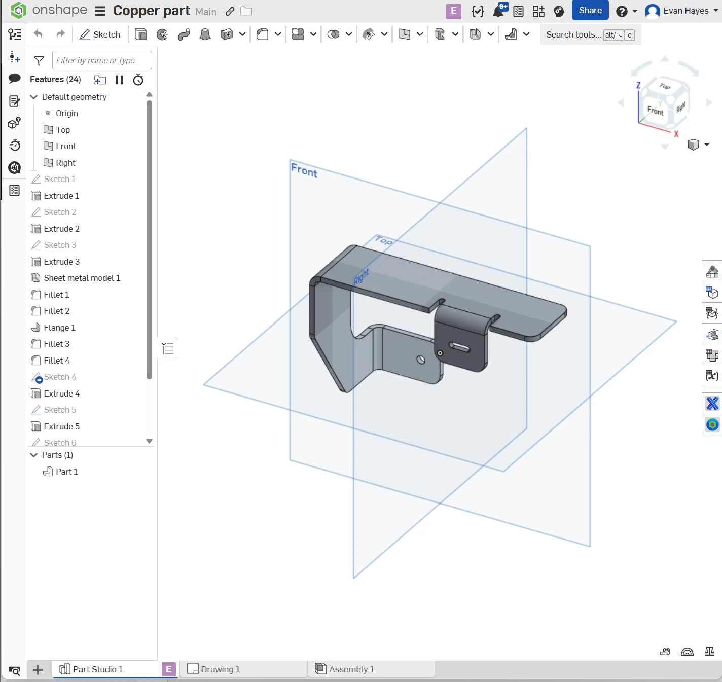
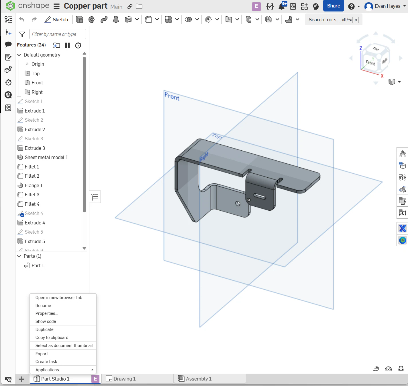
A formed part in an Onshape Part Studio. The Sheet metal model 1 entry in the feature list is what makes this a sheet metal part rather than a solid — it holds the thickness and bend radius, and it is why Onshape can flatten it at all. This is the model you want to send us: folded, in 3D.
STEP is the file format we most want to receive for a formed sheet metal part. It is a neutral solid-model format — not tied to any one CAD system — and it carries the real 3D geometry of your part as you designed it. Onshape exports it in about six clicks.
The important part is which geometry you send. For a part with bends, send the folded 3D model, not a flat pattern. That surprises people, so it is worth spelling out why.
When we unfold your part, the flat blank we cut is not just the sum of the flange lengths. It is shortened by a bend deduction that depends on the material, the exact thickness, the inside radius produced by the punch tip, and the V-opening of the die we are going to run. Those are numbers from our tooling, not from a handbook. If you develop the flat yourself with a generic K-factor and send us that outline, we cut exactly what you drew — and the folded part comes out a few thousandths to a few tenths off on every overall dimension, in a way that is invisible until it does not fit.
Send the folded model and that whole category of error disappears. We derive the flat from your 3D geometry using the deduction for the tooling that will actually form it. If you want to see the numbers we work from, they are published in the Bending Ontology & Material Specs lookup and the Press Brake Tooling Library.
Check the Model First
Thirty seconds of checking in Onshape saves a round trip of emails later. Four things are worth a look before you open the export dialog.
1. Confirm it is actually a sheet metal part
Look in the feature list for a Sheet metal model feature, and look in the Parts list for a part with the folded sheet metal icon. If your part was built as a plain extrude with modeled-in radii and no sheet metal definition, it can still be quoted — but it is worth telling us the intended thickness and bend radius in your order notes, because there is no sheet metal definition in the file for us to read.
2. Confirm the thickness is what you think it is
Onshape's sheet metal model carries a single thickness for the whole part. Make sure it matches a gauge we actually stock, or expect us to come back and ask. Our stocked thicknesses per alloy are listed on the Materials pages. If the part will have perpendicular flanges, set Minimal gap and inside radius from the corner flange Onshape walkthrough before you export — the Sheet metal model dialog is where those numbers live.
3. Make sure nothing is in error
Features flagged with errors or warnings in the feature list mean the geometry Onshape has computed may not be what you intended. Export will often still succeed and hand you a solid that quietly differs from the design. Clear the errors first.
4. Know which workspace you are in
Onshape exports what is in front of you. If you are looking at Main, you get the current, still-editable state of the model. If you have released a version, open that version and export from there so the file you send matches the revision you are approving internally.
Exporting the Part
This is the whole procedure, from an open Part Studio to a .step file in your downloads folder.
-
Right-click the part in the Parts list and choose Export…
The Parts list is at the bottom of the feature list on the left. Right-clicking the part itself — not a feature — is what gives you the part-level menu with Export… in it. This exports that one part and nothing else, which is exactly what you want when quoting a single component.
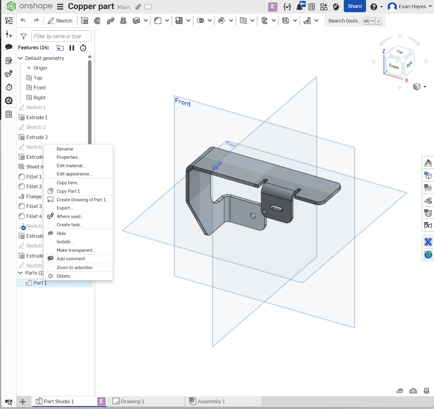
Right-click the part in the Parts list. Export… sits in the middle group of the menu, below Create Drawing of Part 1.
-
Name the file something we can read.
Onshape pre-fills the file name from the tab and part name — typically something like
Part Studio 1 - Part 1. Replace it with your actual part number or a plain description. When a quote covers several parts, file names are how we keep your quantities attached to the right geometry, andPart Studio 1 - Part 1.steptells us nothing.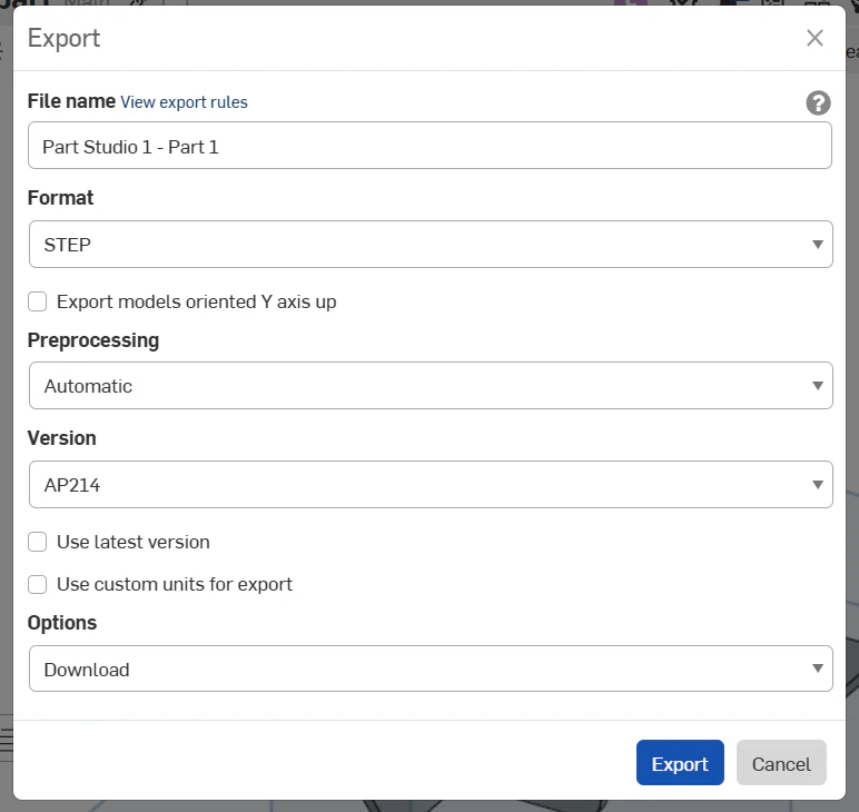
The Export dialog. Everything you need is on this one panel — and every field on it has a sensible default except one.
-
Set Format to STEP.
Onshape remembers the last format you used, so it may already be set. The dropdown also offers Parasolid, ACIS, IGES, STL, 3MF and others. For a fabrication quote, STEP is the one to send — STL and 3MF are mesh formats that throw away the exact surfaces we need, and IGES is a surface format that tends to arrive with gaps.
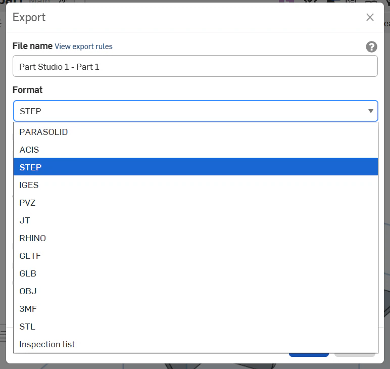
Pick STEP. If you are ordering a 3D printed part instead of a fabricated one, STL or 3MF from this same list is the right choice — see the 3D Printing Design Guide.
-
Leave Version at AP242 or AP214.
These are STEP application protocols — different published editions of the standard. Onshape defaults to AP214, and AP214 is completely fine for us: it carries the solid geometry, which is all a fabricated sheet metal part needs. AP242 is the newer protocol and also works. Avoid AP203, the oldest of the three.
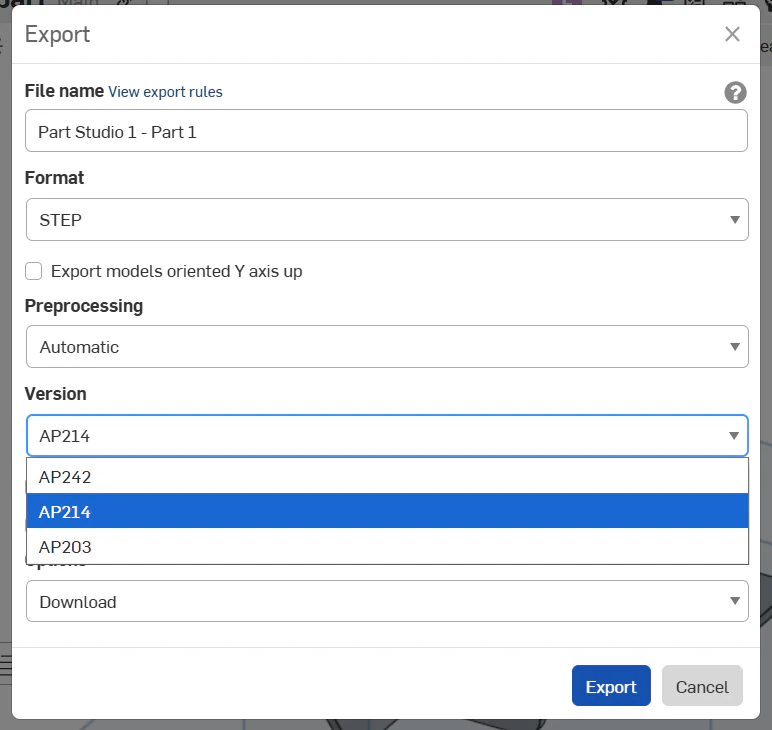
AP242 and AP214 both work. Onshape's default of AP214 needs no changing.
- Leave “Export models oriented Y axis up” unchecked. This rotates the model on the way out to suit software that assumes Y is the vertical axis — a convention from 3D graphics, not from engineering. CAD and CAM treat Z as up. Checking this box lands your part lying on a different axis than you drew it, which is harmless for geometry but confusing for everyone who opens it afterwards.
- Leave “Use custom units for export” unchecked. Unchecked, Onshape writes the file in your document's own units and the part arrives at the size you modelled. This is the one setting on the panel that can silently ruin a part, so it has its own section below. If you do check it, you must then set the Units dropdown yourself — it does not inherit anything.
-
Set Options to Download.
The Options dropdown decides where the finished file goes. Download puts it straight in your browser's downloads folder, which is what you want when the next step is uploading it to a quote. The other entries store the file back into your Onshape document as a new tab, or email a download link.
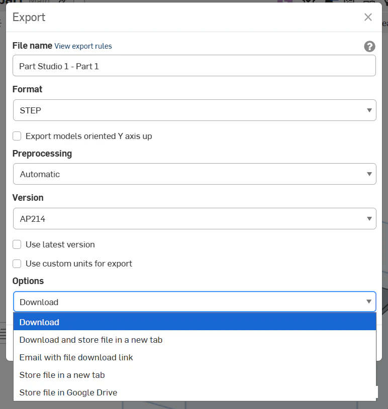
Download is the first entry and the right one here. “Download and store file in a new tab” is a reasonable alternative if you also want a copy archived in the Onshape document as a record of exactly what you sent.
-
Click Export.
Onshape translates the part server-side and the
.stepfile appears in your downloads. Files for a single sheet metal part are typically tens to a few hundred kilobytes — if you get something measured in bytes, the export did not produce geometry and it is worth checking the model for errors before sending it.
What Each Setting Does
The whole dialog in one table, with what we recommend and why.
| Setting | Send us | What it does |
|---|---|---|
| File name | Your part number | Pre-filled from the tab and part name. Rename it. File names are how quantities stay attached to the right geometry on a multi-part quote. |
| Format | STEP |
The output format. STEP is a neutral solid-model exchange format that every CAM system reads, and it preserves exact surfaces rather than approximating them with triangles. |
| Export models oriented Y axis up | Unchecked | Rotates the model so Y becomes the vertical axis, for tools that expect the graphics convention. Engineering software expects Z up. |
| Preprocessing | Automatic |
Lets Onshape decide how to condition the geometry before translation. The default handles normal sheet metal parts without help. |
| Version | AP214 or AP242 |
Which edition of the STEP standard to write. Both carry the solid geometry we need. AP242 is newer; AP214 is Onshape's default and equally usable. AP203 is the oldest and worth avoiding. |
| Use latest version | Unchecked | Leave it alone unless you specifically know you need it. For a straightforward single-document part it changes nothing. |
| Use custom units for export | Unchecked | Overrides the document units with a unit you pick. Unchecked, the file comes out at the size you modelled. Checked, it defaults to Centimeter and you must change it yourself. |
| Options | Download |
Where the finished file goes: straight to your downloads, stored back into the Onshape document as a tab, or emailed as a link. |
The Units Trap
This is the single most common way an Onshape STEP export goes wrong, and it is worth its own section because the failure is silent. Nothing errors. The file opens. The part is just the wrong size.
Tick Use custom units for export and a Units dropdown appears underneath it. It does not default to your document's units, and it does not default to millimeters. It defaults to Centimeter.
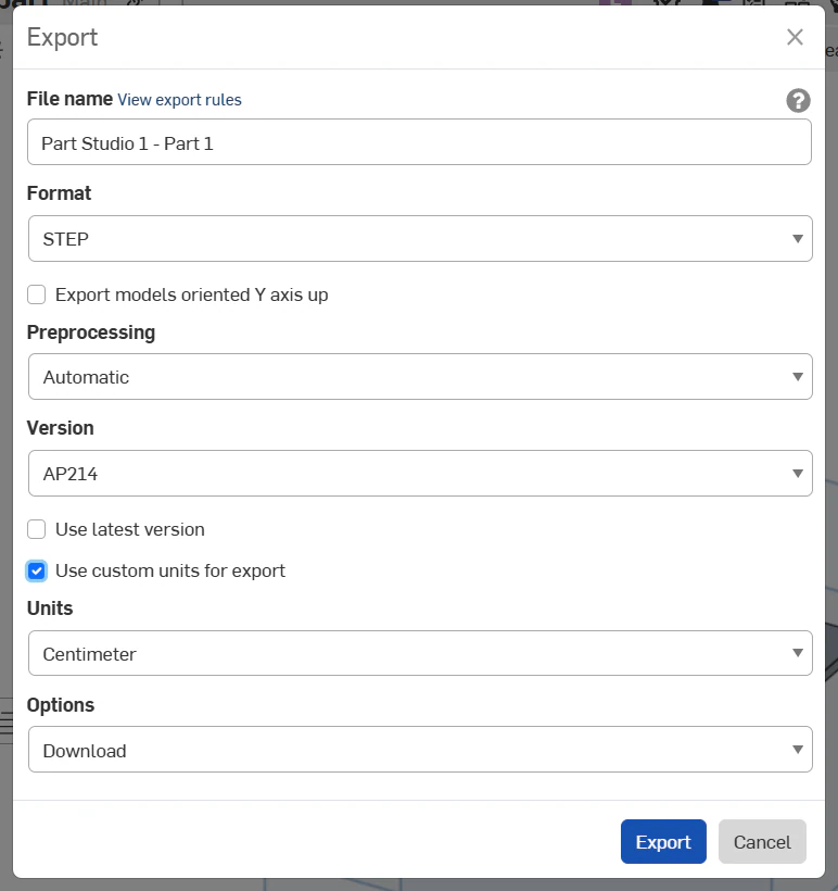
Checking the box reveals the Units dropdown — already set to Centimeter. Almost nobody dimensions sheet metal in centimeters.
Centimeters are a legitimate unit and STEP is perfectly happy to record them, so the file is not corrupt — it is a valid description of a part ten times larger or smaller than you meant, depending on which direction the misreading runs. A 100 mm bracket becomes a 100 cm bracket. That is a metre of aluminum, and it will get quoted as a metre of aluminum.
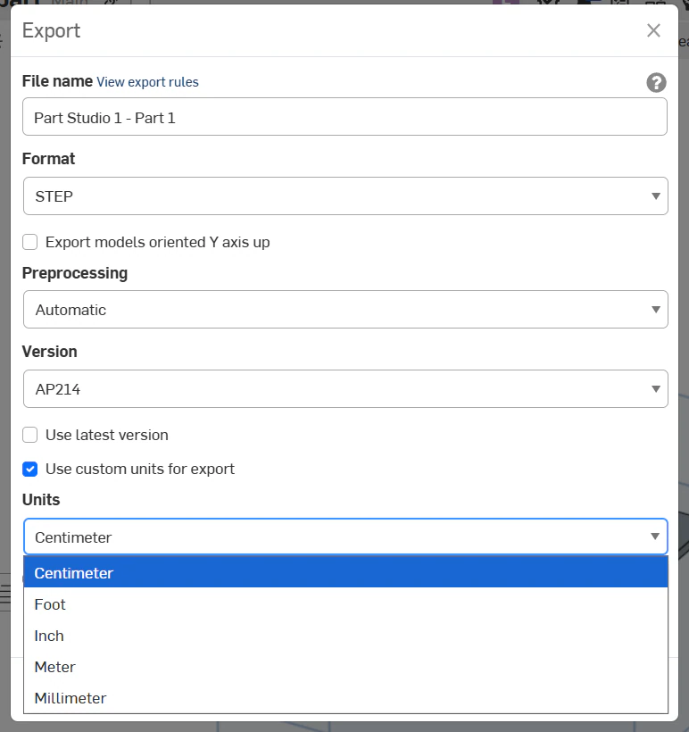
The full list: Centimeter, Foot, Inch, Meter, Millimeter. If you check the box, pick Millimeter or Inch deliberately — whichever your drawing is dimensioned in.
More Than One Part
Right-clicking an individual part exports that part alone. There are two other routes when you have more than one.
Everything in the Part Studio at once
Right-click the Part Studio tab at the bottom of the window and choose Export…. You get the same dialog, but the export covers every part in that studio.
The tab-level menu. Export… here covers the whole Part Studio rather than one part.
Assemblies
If your parts live in an Assembly, you can export from the Assembly tab the same way. That is genuinely useful when we need to understand how parts fit together — but send the individual parts too. We fabricate the components, so the component geometry is what gets programmed, and an assembly file mostly tells us about intent and fitment. If a weldment or a fastened stack-up has fitment that matters, send both and say so in the notes.
Assembly context is also where clearance problems show up. If flanges land close to one another, it is worth reading Part-on-Part Collision before you order — a formed flange travels past its final angle during the bend, and gaps that look fine in CAD can be a crash at the brake.
Flat Pattern vs. Folded Model
Onshape can flatten a sheet metal part for you, and it is tempting to send that instead. Here is how to decide.
What we would ask you not to do is develop the flat pattern yourself for a part that has bends, and send us that outline as the thing to cut. Not because it is wrong of you — it is standard practice in shops that cut and form on known tooling — but because your K-factor was chosen for tooling you do not know we have. The Bend Affected Zone guide covers the related trap of features placed too close to a bend, which no amount of correct unfolding will rescue.
If you have a reason to control the flat yourself — you are matching an existing part, or you have a blank that has already been proven — send both the flat and the folded model and tell us the flat is the controlling geometry. We will cut what you specify.
Export details for DXF from Onshape and from other CAD systems are in How to Prepare Your CAD File.
What STEP Doesn't Carry
A STEP file is geometry. It is very good geometry — exact surfaces, watertight solids, no approximation — but it is not a drawing, and there is a specific list of things it does not bring with it.
- Material. Nothing in the file says 5052-H32 rather than 304 stainless. Even if you assigned a material in Onshape, do not rely on it surviving the translation. Specify material in your order.
- Tolerances. STEP records nominal geometry. There is no way to see from the file that one hole spacing is critical and the rest are not. If something needs to be tighter than our standard tolerances, it needs a drawing — see the Engineer's Guide to GD&T.
- Finish. Powder coat colour, anodize type, brushed vs. mill finish — none of that is geometry. Pick it in the quote, or state it in the notes. Powder coating and anodizing have their own guides.
- Hardware and threads. A modelled hole is a hole. If it needs a PEM insert, a tap, or a countersink to a specific angle and depth, call it out. Countersinking for Sheet Metal covers what we need to know.
- Bend order or forming intent. The folded model tells us where the bends are; it does not tell us that one flange must be formed last for clearance reasons. If you know a sequence matters, say so.
- Sheet metal features as features. STEP is a dumb solid: no history, no parametric sheet metal definition, no bend table. That is fine — we unfold from the geometry — but it means the file carries no thickness label for us to read, only a thickness we measure.
Pre-Upload Checklist
Run this before you upload. It takes under a minute.
- Folded model, not flat pattern — for any part with bends.
- Format is STEP — AP214 or AP242, not AP203.
- “Use custom units for export” is unchecked — or set deliberately to Millimeter or Inch, never left on Centimeter.
- “Y axis up” is unchecked — so Z stays vertical.
- File is named for your part — not
Part Studio 1 - Part 1. - One file per unique part — with its own quantity on the quote.
- No feature errors in the model — a part that computes wrong exports wrong.
- Thickness matches a stocked gauge — check the Materials pages.
- Units stated in your order notes — four words, zero ambiguity.
- Drawing attached if tolerances are tight — anything beyond our standard tolerances needs to be called out.
Troubleshooting
| Symptom | Cause and fix |
|---|---|
| Part came back quoted at 10× or 1/10 the size | “Use custom units for export” was checked and left on Centimeter. Re-export with it unchecked, or with Units explicitly set to Millimeter or Inch. |
| Export produced a tiny file with no geometry | The part had errors, or nothing was actually selected when you invoked Export. Clear feature errors, confirm the part is listed under Parts, and export from the part's own right-click menu. |
| We asked which of the parts in your file to quote | The export came from the Part Studio tab rather than a single part, so all parts in the studio landed in one file. Export each part separately, or tell us the quantities per part in the notes. |
| The part is lying on an unexpected axis | “Export models oriented Y axis up” was checked. Harmless to the geometry, but re-export without it to keep Z vertical. |
| Onshape offers no STEP option for what you selected | You are probably on a Drawing tab rather than a Part Studio or Assembly. Drawings export to PDF and DXF/DWG; solid geometry comes from the Part Studio. |
| Your flat pattern and our flat pattern disagree | Expected, and not a problem. We unfold with the bend deduction for the tooling that will run the job. Overall folded dimensions will match your model; the blank size will not match a blank developed with a generic K-factor. |