What Is Fiber Laser Cutting?
Beyond "a laser cuts metal." This is the nitty-gritty — how a beam of near-infrared light is born inside a glass fiber, focused to a spot finer than a human hair, and used with high-pressure gas to slice through steel at the speed of light.
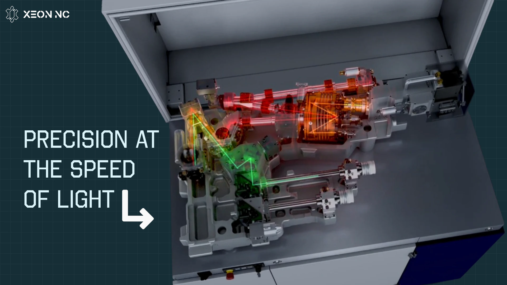
A fiber laser cutter doesn't really "burn" metal the way a torch does. It concentrates an enormous amount of light energy onto a microscopic point — so much that the metal there instantly melts or vaporizes — then blows the liquid away with a jet of gas, moving that point along your part's outline.
The word "fiber" describes where the light comes from: the laser beam is generated and amplified inside a doped optical fiber rather than a tube of gas or a slab of crystal. That one design choice gives fiber lasers their signature combination of efficiency, beam quality, reliability, and raw cutting speed. To really understand the process, it helps to follow the light from where it's created all the way down to the kerf it leaves behind.
Generating the Beam: Light Born in Glass
The heart of the machine is the fiber laser source. Instead of mirrors bouncing through a gas, the "active medium" is a long, thin optical fiber whose glass core is doped with a rare-earth element — usually ytterbium (Yb).
- Pump diodes — banks of semiconductor laser diodes pour light into the fiber, exciting the ytterbium atoms to a higher energy state.
- Stimulated emission — as those atoms relax, they release photons all at the same wavelength and phase, amplifying as they travel down the fiber. This is the "laser" effect (Light Amplification by Stimulated Emission of Radiation).
- ~1.06–1.07 µm wavelength — the resulting beam sits in the near-infrared. That short wavelength is absorbed far better by metals than older technologies, which is the whole game for cutting.
- Exceptional beam quality — because the light is confined inside a tiny fiber core, the beam is naturally clean and tightly focusable.
From Source to Sheet: The Beam's Journey
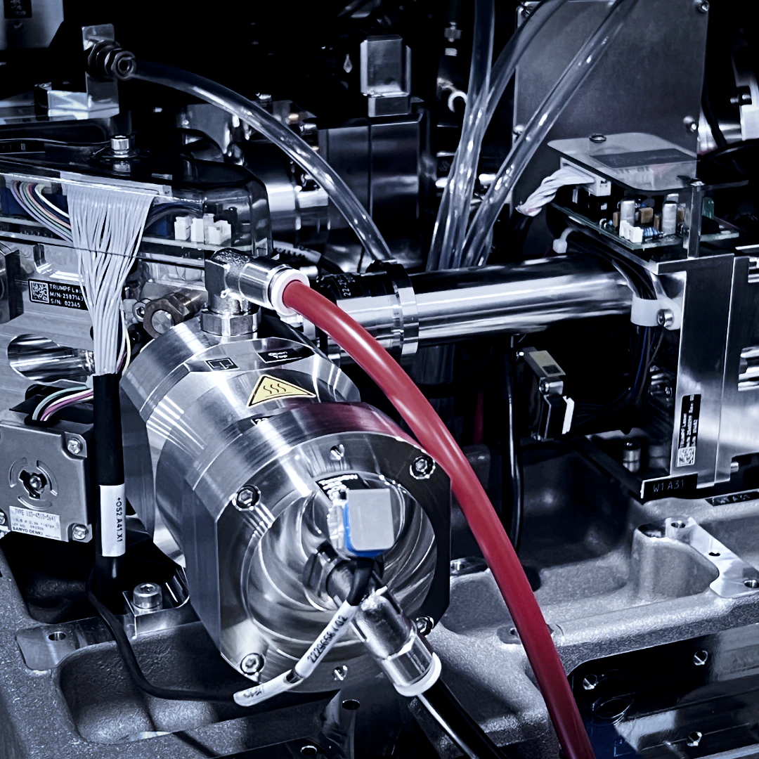
Once the beam exists, it has to travel from the source to the surface of your material and arrive as a focused, perfectly aligned point of light. In a fiber laser there are no delicate flying mirrors — the beam rides inside a flexible fiber-optic cable, then through a compact cutting head.
-
Transport fiberThe raw beam travels from the source through an armored fiber-optic cable to the cutting head — loss-free and immune to the misalignment that plagues mirror-based systems.
-
CollimatorThe beam exits the fiber diverging, so a collimating lens straightens it into a parallel column of light before focusing.
-
Focusing lensA focusing lens drives that column down to a tiny waist — a spot often just
~100–300 µmacross. This is where the energy density becomes extreme. -
Nozzle & assist gasThe focused beam exits through a nozzle that also delivers high-pressure assist gas coaxially with the beam, right at the cut zone.
-
Capacitive height controlThe head continuously senses and holds its standoff from the sheet, keeping the focus exactly where it needs to be even over warped or moving material.
How the Beam Actually Cuts Metal
Everything up to now exists to create one thing: an almost unimaginable concentration of energy on a single point. When that focused spot lands on metal, the physics happen fast.
Spot Size
at the Spot
Power Available
- Absorption & heating — the metal absorbs the concentrated light and its temperature spikes past melting point in microseconds.
- Melt & vaporize — a tiny pool of molten (and partly vaporized) metal forms exactly at the focal point, no wider than the beam.
- Melt ejection — the coaxial assist gas blasts that molten material straight down and out the bottom of the cut, clearing the way.
- Motion makes the cut — the head traces your contour, and the continuous melt-and-eject leaves behind a clean, narrow kerf in the exact shape of your part.
Assist Gas: Nitrogen, Shop Air & Oxygen
The assist gas isn't just there to clear debris — the gas you choose fundamentally changes the cut. Three options cover almost everything: nitrogen, oxygen, and plain shop air — and they cut by different mechanisms at very different costs.
- Inert — it doesn't react with the metal
- Purely blows molten material out of the kerf
- Leaves a clean, bright, oxide-free edge
- Ideal for stainless & aluminum that will be welded, coated, or left cosmetic
- Highest gas cost — high pressure and volume
- Just clean, dry compressed air — ~78% N₂, 21% O₂
- By far the lowest-cost assist gas — no cylinders or bulk tank, only the compressor
- The nitrogen content blows a clean melt while the oxygen adds a little energy
- For thin-to-medium gauge it typically cuts faster than oxygen
- Leaves a light oxide — between nitrogen and oxygen edges
- Needs very clean, dry, oil-free air; limited on thick plate
- Reacts exothermically with the metal — the burn adds energy
- That extra heat lets it cut thicker carbon steel than air can
- Leaves a heavier oxide layer on the cut edge
- Lower gas pressure than nitrogen cutting
- Best for heavy mild steel where edge oxide is acceptable
The Parameters That Matter
A great cut is a recipe. For every material and thickness, our machines run a tuned set of parameters — nudge any one and the edge quality, speed, or reliability changes.
- Power & speed are a pair. Too fast and the beam can't fully sever the material; too slow and you waste heat and widen the kerf. They're balanced for each thickness.
- Focal position sets how the energy is distributed through the sheet's thickness — critical for a square, dross-free edge.
- Gas pressure controls how cleanly the melt is ejected. Clean nitrogen edges need high pressure; oxygen cutting runs lower.
- Standoff must stay constant, which is why capacitive height sensing follows the sheet in real time.
Why Fiber Beat CO₂
For decades, CO₂ lasers dominated metal cutting. Fiber lasers have largely displaced them for sheet metal — and the reasons are concrete, not marketing.
| Attribute | Fiber Laser | CO₂ Laser |
|---|---|---|
| Wavelength | ~1.06 µm (near-IR) | 10.6 µm (far-IR) |
| Beam delivery | Flexible fiber cable | Mirrors & alignment |
| Wall-plug efficiency | ~30–40% | ~10% |
| Thin-sheet speed | Significantly faster | Slower |
| Reflective metals | Cuts Al, Cu, brass well | Struggles / risky |
| Maintenance | No laser gas, no mirrors | Mirrors, gas, more upkeep |
The short version: fiber lasers turn more electricity into usable light, deliver it without fragile optics, cut thin and reflective material faster, and need far less maintenance. That's why our floor runs fiber.
What It Means for Your Parts
All of this physics shows up in the part you receive — in three things especially worth understanding as a designer:
- Kerf — the beam removes a narrow strip of material as it cuts. Our software compensates for that width so your dimensions land on target. Dig into it in our laser kerf guide.
- Heat-affected zone (HAZ) — a thin band beside the cut sees brief intense heat. Fiber's fast, focused cut keeps it small — see the HAZ guide for how it affects material.
- Edge quality & tolerances — clean, square, repeatable edges across a full sheet. To design parts that exploit all of this, read our fiber laser design guide.