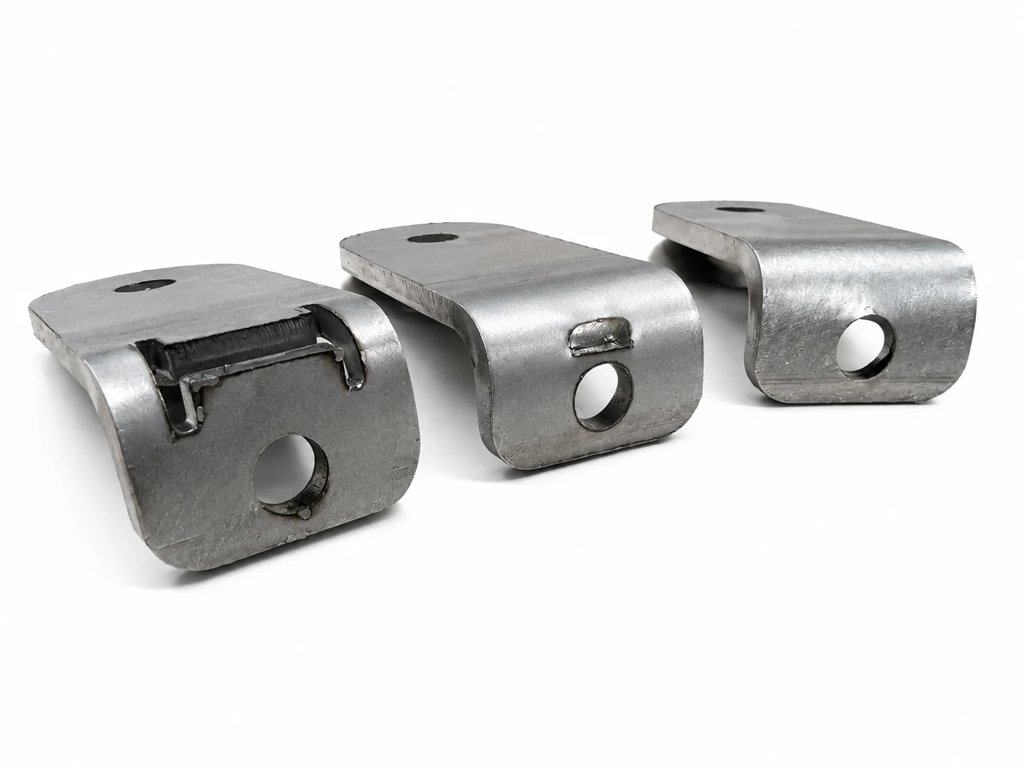
The hole is not pulled through by accident.
The bend is a moving field of tension and compression. Put a hole inside that field and the metal does what every loaded system does: it finds the path of least resistance.
During forming, the material outside the neutral axis stretches while the material inside it compresses. That deformation extends beyond the visible radius into the surrounding flange. A nearby hole removes cross-section from the exact region trying to carry the load. The remaining ligament stretches first. The face dishes. The hole elongates, lifts, or migrates toward the bend.
The final part may still look like a bracket. Functionally, it can be compromised: a fastener head no longer seats flat, a locating pin no longer finds nominal position, and a bearing surface becomes an irregular edge. That is hole pull-through.
First remove the conflict. Then control it.
The preferred solution is still distance. Move the hole outside the bend and die-shoulder keep-out, move the bend, or add the hole after forming. If none of those are available, relief geometry can turn uncontrolled deformation into a bounded event.
A relief works by creating a free edge between the bend and the protected feature. Material adjacent to that edge can rotate, stretch, or separate without dragging the hole boundary through the same displacement. The feature is no longer fully coupled to the bend.
Move or post-process
Move the hole, move the bend, or drill the hole after forming. The part retains a continuous load path and the feature is controlled by position rather than damage management.
Isolate the region
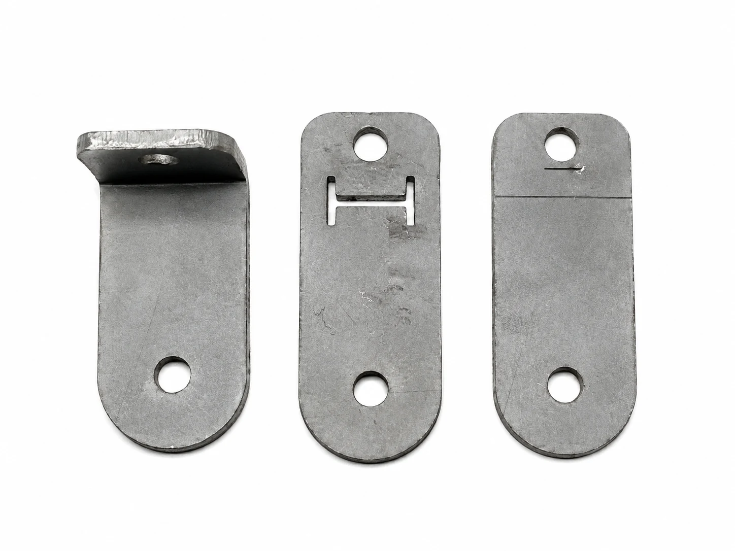
A bow-tie or H-style cutout removes the material most likely to pull the hole into the bend and leaves a deliberately bounded flexure or island.
Interrupt the path
A straight or radiused slit creates a free edge between the hole and bend, redirecting strain with less removed material and less isolation.
The bow-tie relief: isolate the deformation.
Use the larger relief when the protected feature matters more than continuity through the local section.
The bow-tie/H-style geometry uses a transverse opening with radiused end slots to separate the hole region from the bend corridor. Instead of asking a thin ligament to absorb strain and remain dimensionally stable, the design removes that contested material or reduces it to a deliberate compliant bridge.
Pull-through, local dishing, and ovalization when the hole must remain close to the bend. The two end reliefs spread rotation across a broader boundary instead of letting a single point carry it.
More net section than a simple slit. The remaining bridges become the new load path and must be wide enough for forming, handling, and service loads.
Span the deformation corridor that would otherwise connect the bend to the hole. Terminate every cut with a radius or round end and keep the relief clear of the functional hole boundary.
Access covers, locating tabs, sensor mounts, light brackets, and other secondary structures where local feature position matters and the relieved section is not the primary load path.
The relief slit: give the strain a line to follow.
Use the simpler cut when a full isolation relief removes too much material and the deformation only needs to be redirected, not fully detached.
A slit placed between the hole and bend introduces a free edge across the local load path. During forming, the sheet can open or rotate along that edge before the displacement reaches the hole. It is a smaller geometric intervention, and that is both its advantage and its limitation.
Localized pull-through where one clear free edge is enough to interrupt the strain path between the bend and protected hole.
More surrounding material than the bow-tie option. The part can retain greater net section and in-plane stiffness, depending on slit length and orientation.
The slit ends carry elevated stress. Never end a structural slit in a sharp laser corner; use round termination holes, generous radii, or a dog-bone end sized for the process.
Low-to-moderate load brackets, prototypes, and geometries where the cut can be placed outside the dominant service-load path and inspected after forming.
The intervention solves one failure by introducing another risk.
A cleaner hole is not the same thing as a stronger part. Every relief cuts across a load path. The design has to account for what remains.
The trade is direct: the more completely the relief isolates the hole from forming strain, the more completely it can isolate that region from service load. This may be acceptable. It may even be desirable. But it cannot be invisible.
Do not use these features by default in lift points, restraints, pressure boundaries, crash structures, primary chassis members, fatigue-critical mounts, or any safety-critical load path. In those cases, move the feature, change the architecture, add the hole after forming, or obtain engineering approval backed by analysis and test.
Select by mission, not appearance.
Start with the function the part cannot lose. Then choose the least invasive geometry that protects it.
| Strategy | Hole control | Section retained | Fatigue sensitivity | Use when |
|---|---|---|---|---|
| Move the hole or bend | High | Highest | Lowest | Interfaces and packaging still have room to change. |
| Hole after forming | Highest | Highest | Low | Location and circularity are critical enough to justify another operation. |
| Bow-tie / H relief | High | Lowest | Moderate to high | The hole must be isolated and the local section is secondary. |
| Straight relief slit | Moderate | Moderate | High at ends | A small interruption redirects enough strain and section loss must be limited. |
| Accept distortion | Low | Highest | Unchanged | The hole is a loose pass-through, drain, or non-locating feature with explicit tolerance. |
Prototype the mechanism, not just the shape.
A relief is coupled to the complete forming system. Validate it in the material and process that will actually ship.
Seven gates before the part ships.
The relief is ready only when the hole and the new load path are both acceptable.
Send the model. Keep the design intent attached.
Upload the formed STEP and identify the protected hole, the relief geometry, and the service load. We will review the feature against the tooling and form a representative test before production when validation is required.
Upload your STEP →