A practical path from a folded CAD model to a clean, measurable part—with real rules for material, tooling, flanges, reliefs, features, tolerances, and bend sequence.
Design Guide 01 / Formed Parts12 minute read
MODEL / MATERIAL / TOOLING / SEQUENCE
Air-bend range
30°–135°
Standard angle
±0.5°
Bend length
UP TO 120 IN
Preferred model
FORMED STEP
4T
Start with enough flange
A useful early-design minimum. Final support follows the selected V-die and angle.
R + 2T
Protect nearby features
Keep the edge of holes and slots beyond the bend-affected zone.
≥ 1T
Relieve terminating bends
Use at least one material thickness of relief width where a bend stops.
ACB
Measure during forming
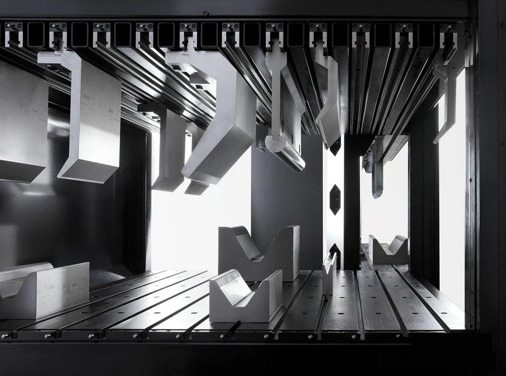
Optical angle feedback compensates for springback at the brake.
The source of truth is the geometry you need after bending—not an unverified flat pattern built around a generic K-factor.
A press brake changes more than an angle. Material stretches across the outside of the bend, compresses at the inside radius, and recovers through springback after the load leaves. The punch, V-die, alloy, temper, grain direction, sheet thickness, and bend sequence all change the result.
Model the finished part as sheet metal, assign the real material and thickness, and give each bend a realistic inside radius. Xeon NC can then develop the blank around the tooling that will actually form it.
Your model defines the destination. The tooling defines the route.
Preferred source of truth
Send the folded model
STEP or STP solid with constant wall thickness
True cylindrical bends with a stated inside radius
Optional drawing that identifies functional dimensions
Material, thickness, finish, and quantity confirmed
Common source of ambiguity
Avoid unsupported assumptions
Flat DXF with no bend direction or formed reference
Zero-radius corners modeled as press-brake bends
Blanket tight tolerances on every dimension
A CAD K-factor treated as production bend data
02 / File Package
Give geometry and intent separate jobs.
The 3D model carries shape. The drawing carries what matters. Together they remove the guesswork from formed-part programming.
RECOMMENDED PACKAGE / FORMED PARTSTATUS: READY
STEP / STP
Folded solid model with constant thickness, real bend radii, and no overlapping faces.
Required
PDF
Datums, critical dimensions, general tolerance, threads, hardware, grain, and finish notes.
Helpful
DXF / DWG
Flat reference or 2D-only part. Include bend centerlines, direction, angle, and a formed view.
Reference
ORDER DATA
Material family, exact thickness, finish, quantity, and any mating-part priority.
Confirm
Do not double-control the flat and the formed part.If the outside dimensions of the formed part are critical, make those the controlled dimensions. A flat length driven by different bend data can conflict with the finished geometry even when both files are internally consistent.
03 / Bend Data
Radius, K-factor, allowance, and deduction are one system.
A flat pattern becomes reliable only after material and tooling are defined. Change either one and the developed blank changes with it.
Inside radius / Ri
TOOL + MATERIAL
The radius formed on the inside surface. It is influenced by V-opening, punch tip, alloy, temper, thickness, and forming method.
K-factor / K
NEUTRAL AXIS ÷ T
The neutral-axis location expressed as a fraction of thickness. It is process data, not a universal material constant.
Bend allowance / BA
ARC IN THE FLAT
The developed length consumed by the bend region along the neutral axis.
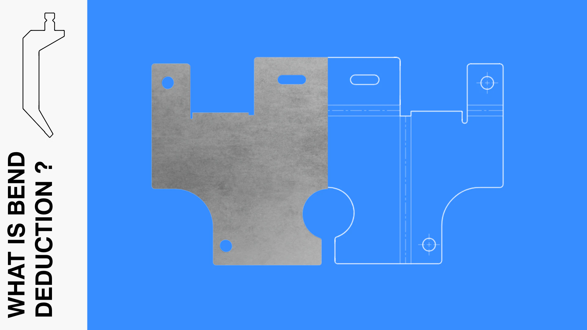
Bend deduction / BD
A + B − FLAT
The amount removed from the sum of outside flange dimensions to calculate the flat length.
Use the Xeon NC bending ontology and material lookup for the V-die, inside radius, K-factor, minimum formed flange, and bend deduction assigned to each supported material and thickness.
Developed lengthBend deduction is not a correction added after the model. It is the relationship that lets the flat blank produce the required outside dimensions after forming.
04 / Geometry Rules
Give the material room to move.
These rules are conservative early-design checks. The quote preflight remains the final authority because it tests the complete part against real tooling.
01
Start with a formed flange of at least 4T.
Both sides of the bend need support across the V-die shoulders. The exact minimum grows with die opening, radius, thickness, and angle.
MIN FLANGE ≈ 4 × T / EARLY DESIGN
02
Use a material-appropriate inside radius.
Use 1T as a starting point for mild steel and 5052-H32 aluminum. Harder tempers need more room: begin near 3T for 6061-T6 and 4T for 7075-T6, then confirm against the selected thickness and tooling.
Ri ≥ 1T / DUCTILE SHEET
03
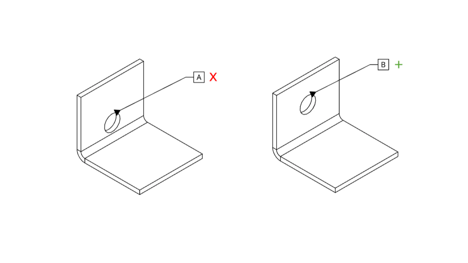
Keep holes and slots out of the bend-affected zone.
Measure from the feature edge to the bend tangent. Features placed closer can elongate, pull toward the bend, or become visibly oval.
FEATURE EDGE ≥ Ri + 2T FROM TANGENT
04
Relieve every bend that terminates.
When a bend stops at a tab, notch, or adjacent wall, the relief gives displaced material an intentional place to flow instead of tearing the corner.
WIDTH ≥ T / DEPTH ≥ Ri + T
05
Bend across the rolling direction when cracking matters.
A bend line perpendicular to the material grain is more forgiving. Call out grain direction on the drawing when surface cracking, cosmetic finish, or fatigue life is critical.
Feature clearanceThe bend influences a zone, not a single line. Move functional holes beyond that zone or plan a post-bend operation.
Need a feature closer than the guideline?Do not hide the conflict. Flag the feature as functionally critical and send the mating-part requirement. Alternate tooling, a larger relief, or a post-bend drilled feature may solve the problem.
05 / Channels, Offsets & Boxes
Every added bend changes the next one.
Multi-bend parts are governed by access, backgauge contact, collision, and escape—not only by whether each bend is valid in isolation.
Profile
Primary design check
Common risk
Best file signal
L-bracket
Minimum supported flange and inside radius
Short leg tipping into the V-die
Folded STEP with one clear bend
U-channel
Inside width, flange height, and punch clearance
First wall blocks the second bend
Finished inside dimensions identified
Z-offset / joggle
Bend-to-bend spacing and opposing directions
Offset too tight for two independent hits
Offset height and parallelism controlled
Box / enclosure
Gooseneck access, corner reliefs, and escape path
Last bend traps the part on the tool
Seams and mating faces clearly prioritized
Odd flange
Straight reference edge for gauging
Irregular edge cannot locate repeatably
Add a removable tab or a gauge surface
For channels and boxes, dimension from the face that locates the assembly. Do not chain every flange from the previous bend. The collision and sequencing guide shows why a geometrically valid final shape can still have an impossible route through the brake.
06 / Tolerances & Drawings
Control the function, not every edge.
Formed dimensions inherit material variation, backgauge positioning, angular error, and every re-gauging operation between the datum and the feature.
±0.5°
Standard bend angle
Measured and corrected with ACB where the geometry provides a valid optical surface.
PER HIT
Dimensional stack
Each setting adds its own band. Dimensions across multiple bends accumulate more variation.
DATUM
Functional reference
Dimension holes and mating faces from the surface that locates the part in the assembly.
A long flange turns a small angular band into visible movement at the tip. If the tip position is critical, identify it explicitly. If a hole pattern is critical, baseline it from a stable datum instead of from a formed edge several bends away.
Drawing practice
Controls that help
General tolerance block for ordinary dimensions
Specific callouts only on functional features
Datums chosen from mating or seating faces
Reference dimensions shown in parentheses
Drawing conflict
Controls that fight
Every flange and the overall all tightly toleranced
Flat length and formed outside dimensions both controlled
Hole locations chained through several bends
Nominal dimensions with no datum or tolerance basis
A ten-minute CAD review can prevent a revision cycle after quoting. Check each line that is true for the part you are sending.
FORMED PART / RELEASE CHECK0 / 10 READY
08 / Submit the Part
Preflight makes complexity legible.
You do not need to choose the punch, die, K-factor, or bend sequence before asking for a quote. You do need to make the finished intent unambiguous.
Upload the formed model, select material and thickness, and attach the drawing when dimensions, hardware, grain, or finish need special control. Xeon NC will read the bend set, assign tooling, validate the deformation zones and collision envelope, then develop the production flat.
Send the formed STEP and the drawing that explains what matters. We will turn that intent into tooling, sequence, flat geometry, and a production-ready quote.