Bending / Xeon NC

How close can a hole be to a bend?

Two different things can ruin a hole near a bend line: the metal stretching around it, and the die shoulder sitting directly underneath it. Most guides only cover the first one—and the second is usually the larger number.

Design Guide / Feature Placement13 minute read
Bend simulator cross-section showing the punch, V-die, and the two die shoulder contact points under the sheet
DIE CONTACT / KEEP-OUT
Design minimum
0.63 × V
Hard floor
V ÷ 2
Deformation
Ri + 2T
Check it in
FLAT VIEW
EDGE
Measure from the hole edge
Not the center. A bigger hole at the same center is a closer hole.
BEND LINE
Measure to the centerline
On the flat pattern, from the hole edge to the bend centerline—the convention used throughout this guide.
0.63 × V
The number that governs
Published on every material page as Min Hole / Cutout from Bend Line.
3243
The code you will see
The quote warning raised when a hole or cutout sits too close to a bend.
←  Back to all guides
01 / The Short Answer

Use the number on your material page.

Every Xeon NC material page publishes a row called Min Hole / Cutout from Bend Line for the exact gauge you are ordering. That value already accounts for the tooling we will use, and for almost every material we form it is the larger of the two constraints in play.

The value equals roughly 0.63 × the V-die opening, measured from the edge of the hole to the bend centerline on the flat pattern. For 0.060″ mild steel formed in our 12 mm die, that is 0.298″. Put the hole edge that far from the bend line and neither failure mode described below can reach it.

If you want to understand why that number is what it is—or you need to defend a feature that has to sit closer—the rest of this guide takes it apart.

A hole near a bend has two enemies. Only one of them is stretch.
Constraint 01 / Deformation
Ri + 2T
The metal stretches

Material inside the bend-affected zone flows toward the weakest point. A hole is the weakest point, so it elongates and drifts. Use Ri + 3T for stainless and 6061.

Constraint 02 / Tooling
V ÷ 2
The die is underneath

The sheet rests on the two die shoulders at ±V/2 from the bend line. A hole there is being loaded directly by the tooling. This is a hard geometric floor, not a guideline.

Design to this
0.63 × V
The published minimum

The die-contact region from the bend line, listed per gauge on every material page. It clears the shoulder with margin and, except on heavy stainless, also clears the deformation zone.

Worked example — 0.060″ (16 Ga.) mild steel, Ø0.25″ hole.Tooling is the 12 mm V-die, inside radius 0.076″. Deformation limit Ri + 2T = 0.196″. Die shoulder floor V/2 = 0.236″. Published design minimum 0.298″. The hole edge goes at least 0.298″ from the bend centerline—and the screenshots further down show exactly what the simulator does at 0.158″ and at 0.315″.
02 / Measuring It Correctly

Three ways to state the same distance.

Most disagreements about hole spacing are not disagreements about the number. They are disagreements about where the two ends of the tape measure go.

Published rules of thumb are quoted from the bend line, from the bend tangent, to the hole center, and to the hole edge—often without saying which. Those choices differ by more than the tolerance on the feature. Everything in this guide is measured from the edge of the hole to the bend centerline, on the flat pattern.

DATUM CONVENTION / FLAT PATTERNEDGE → CENTERLINE
Where hole-to-bend distance is measured A flat pattern strip with a bend centerline, two bend tangent lines either side of it, a die shoulder keep-out band, and a hole. The measured distance runs from the near edge of the hole to the bend centerline. BEND LINE THIS DISTANCE HOLE EDGE, NOT CENTER BEND TANGENTS DIE SHOULDER BAND (±V/2) FLAT PATTERN
01
Measure from the hole edge, not the center.
Enlarging a hole without moving its center moves the hole closer to the bend. A Ø0.50″ clearance hole on the same center as a Ø0.25″ hole has given up 0.125″ of clearance.
02
Measure to the bend centerline, not the tangent.
The tangent moves when the radius changes; the centerline does not. Working from the centerline keeps the number stable and matches the die geometry, which is symmetric about that line.
TANGENT ≈ CENTERLINE − (Ri + T)
03
Measure on the flat pattern, not the folded model.
The bend consumes material. A distance that looks correct on the formed part can be short on the developed blank, which is where the die actually meets the sheet.
04
Apply it to slots, notches, and cutouts too.
Nothing about the rule is specific to round holes. Any opening removes material the bend needs, and any opening can sit on a die shoulder.
03 / Failure One: Stretch

The hole pulls toward the bend.

This is the failure mode everyone knows, and it is real—it is just not usually the binding one.

During forming the outer fiber of the bend stretches and the inner fiber compresses. That strain does not stop cleanly at the tangent line; it fades out across a corridor of permanently deformed material on both flanges. Inside that corridor, the metal flows toward whatever is weakest. A hole is a void with no material to resist, so the strain concentrates around it: the hole elongates along the bend axis, shifts off its nominal position, and the surrounding face dishes.

The result is a fastener that will not seat, a dowel that will not locate, and a hole diameter that no longer matches the drawing. The practical threshold is the inside radius plus two material thicknesses, and stiffer, less ductile material needs more room.
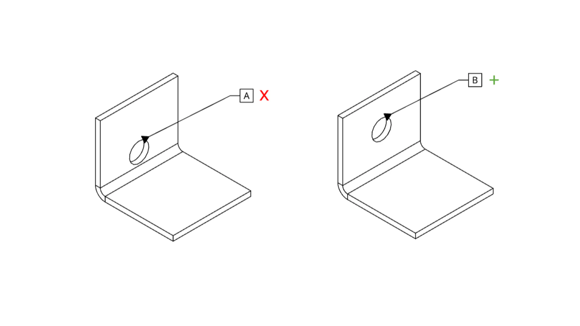
Comparison of a hole placed inside the bend deformation zone becoming oval versus the same hole spaced clear of the bend
DistortionLeft: the hole sits inside the deformation corridor and ovalizes as material flows into it. Right: the same hole moved clear of the corridor forms round and stays on position.
Ductile sheet
Ri + 2T

5052-H32 aluminum, A1008 cold-rolled steel, G90 galvanized, and A36 hot-rolled pickled and oiled.

Work-hardening or hard temper
Ri + 3T

304 and 316 stainless, and 6061. These carry a wider deformation corridor and are the materials where this rule can overtake the tooling limit.

This is the rule behind quote warning codes 3243 and 4243, documented in the DFM rules and error code lookup. The bend-affected zone guide goes deeper on the deformation field itself.

04 / Failure Two: The Die

The part is standing on two lines.

In air bending the sheet touches the tooling in exactly three places: the punch nose, and the two die shoulders at ±V/2 either side of the bend line. Those shoulders carry the entire forming load.

Put a hole on a shoulder and the geometry stops being a stress-concentration question and becomes a contact question. The sheet is being pressed against a hardened steel edge at that exact location, with tonnage behind it. The hole rim gets dimpled, the edge of the opening rolls, and the flange can collapse locally—independently of anything the bend-affected zone is doing.

This is why the die opening, not the bend radius, sets the real floor. And because the die opening grows with material thickness, the keep-out grows with it too.
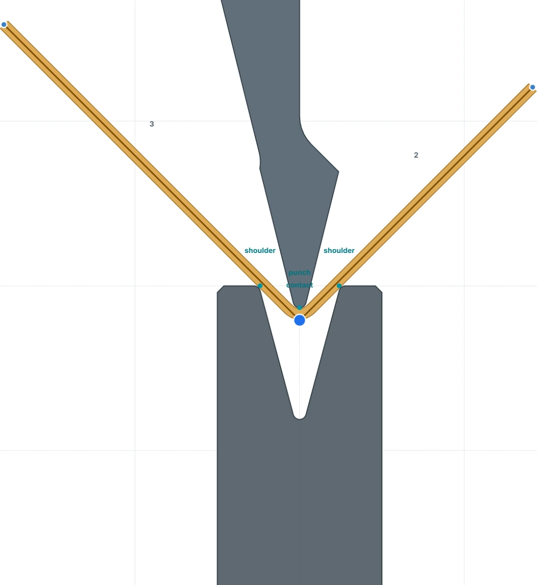
Bend simulator two-dimensional view labelling the two die shoulder contact points and the punch contact point on a formed sheet
Three contactsThe Xeon NC bend simulator marks them directly: two shoulder points where the sheet rests on the die, and one punch contact at the nose. The shoulder markers are the lines a hole must stay off.
The tooling limit is usually the bigger number.On 0.060″ mild steel the deformation rule asks for 0.196″ and the die shoulder sits at 0.236″. A hole at 0.21″ passes the stretch check and still lands on the die. That gap is exactly why the published material-page value is the one to design against.
05 / Your Material Page

The number is already published for your gauge.

You do not have to derive any of this. Open the material page for what you are ordering and read the bend data table.

MATERIAL PAGE / BEND DATAPER GAUGE
Ri
Inside Bend Radius — the radius the selected die actually forms in this gauge.
Given
HOLE
Min Hole / Cutout from Bend Line — the die contact region measured from the bend line. This is the design minimum.
Use this
FACE
Min Hole / Cutout from Outside Face — the same clearance restated from the outside face of the formed part, for checking on the folded model.
Cross-check
FLANGE
Min Flange Length — the same die-contact geometry seen from the other direction. It is the same number, which is not a coincidence.
Related
V / K
Die, punch, V-opening, and K-factor assigned to this material and thickness.
Reference

The hole clearance and the minimum flange are the same value because they describe the same physical fact: the strip of sheet that has to lie flat and unbroken across the die shoulder. A flange shorter than that has nothing to sit on. A hole inside it removes the material that would have been sitting there.

Values marked † are derived from die geometry.The material pages flag these as geometric derivations from the V-die rather than numbers measured on the brake. They are conservative and reliable for design, and we verify on a test bend before a production run.
06 / See It in the Simulator

Stop measuring. Look at it.

The Xeon NC bend simulator draws the die shoulder keep-out directly onto your flat pattern as a hatched red band, and flags any hole that lands inside it.

This turns the whole question into something you can see instead of something you have to calculate. Build the profile, place the hole where the design wants it, and the tool tells you whether the die can live with it.

01
Set the material and thickness.
On the Build tab, pick the material family and enter the exact gauge. This selects the die, and the die is what sets the keep-out width. Units follow the Inches / Millimeters toggle.
02
Build the profile and set the bend length.
Enter the first length, then add flanges with their length and angle. Set Length along bend to the real part width so the blank is the right size.
03
Switch to Flat View.
Use the viewer buttons at the bottom right. The blank unfolds, and every bend gets a blue dashed centerline, a pair of tangent lines, and a hatched red ±V/2 die shoulder band.
04
Set the hole diameter, then click the blank.
Enter New hole Ø under Cutouts and click to place. Drag to move it. The hole list below lets you type exact coordinates instead of eyeballing the position.
05
Read the flag.
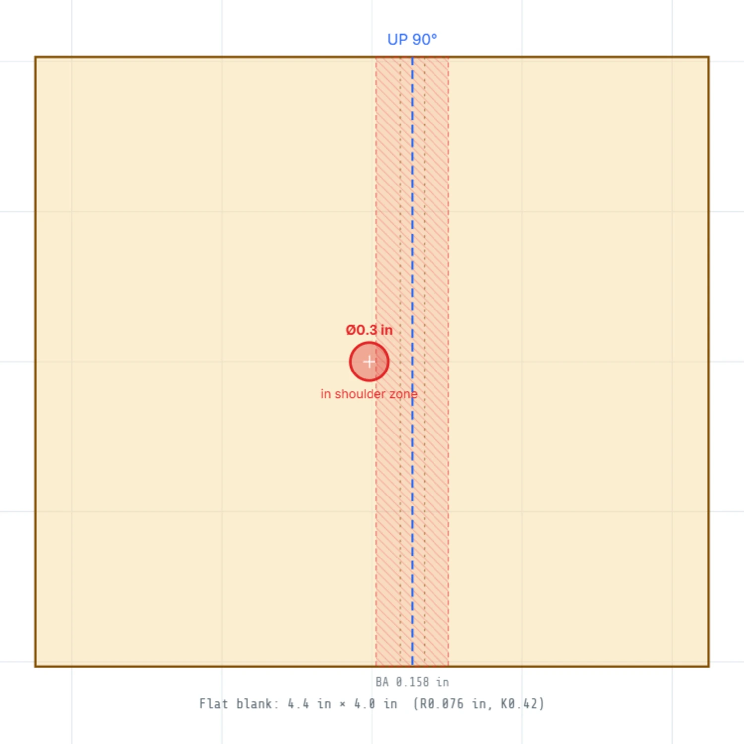
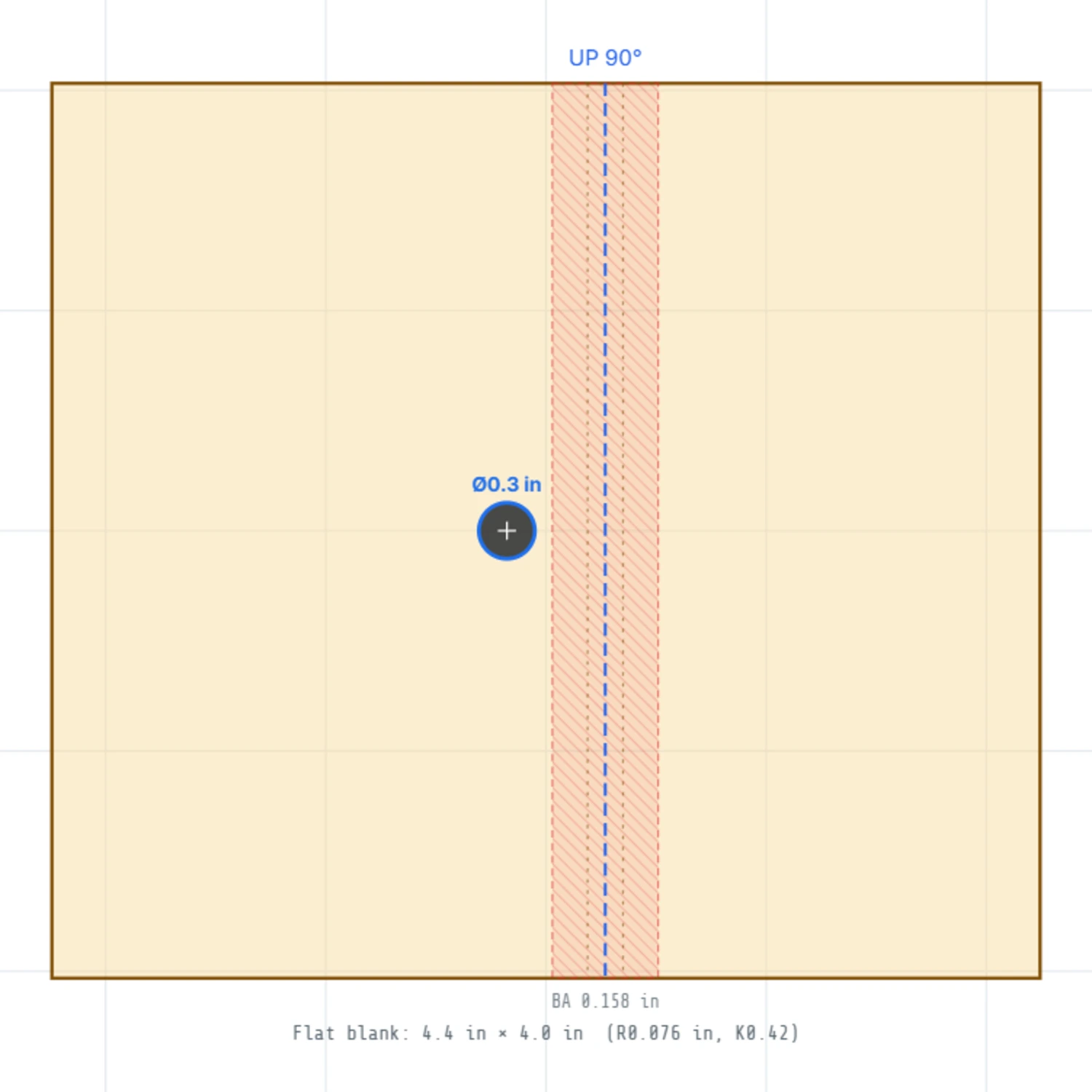
A hole overlapping the band turns red and is labelled in shoulder zone. A hole that clears it renders dark with a blue outline. The blank footer confirms the developed size, the formed radius, and the K-factor used.
06
Cross-check against the material page.
Clearing the hatched band means the die is satisfied. Compare with the published Min Hole / Cutout from Bend Line for your gauge to confirm you also have deformation margin—that value is deliberately larger than the band.
Bend simulator flat view showing a quarter inch hole overlapping the hatched red die shoulder band and flagged in shoulder zone
✗ Rejected / 0.158″ from the bend line
A Ø0.25″ hole on 0.060″ mild steel, placed 0.158″ from the bend centerline. It overlaps the hatched band, so the simulator turns it red and labels it in shoulder zone. It is also excluded from the exported STEP cutouts.
Bend simulator flat view showing the same hole moved clear of the die shoulder band and rendered as an accepted feature
✓ Accepted / 0.315″ from the bend line
The same hole moved out to 0.315″. It clears the die shoulder band and also clears the 0.298″ published minimum for this gauge, so it has deformation margin as well. The flag disappears.

Note what the two frames have in common: the band did not change. It is a property of the die, which is a property of the thickness. The only thing that moved was the hole.

Bend simulator three-dimensional view of the formed L-bracket with the accepted hole in the base flange
Formed resultSwitch to 3D View to see the accepted hole on the folded part. Holes that fail the shoulder check are deliberately left out of the 3D mesh and the STEP export, so an empty face is itself a signal.
The simulator checks tooling contact, not deformation.The hatched band is a strict geometric test against the die: it answers “can this be formed without the tooling touching my hole.” It does not model the stretch corridor. Clearing the band is necessary, not sufficient—the material-page value covers both.
07 / Reference by Gauge

Every die band, all three numbers.

All distances are from the hole edge to the bend centerline on the flat pattern. Design to the fourth column.

ThicknessV-dieHard floor V/2Design minimum 0.63 × VDeformation Ri+2T (3T for SS)What governs
0.020″ – 0.048″W8 / 0.315″0.157″0.198″0.090″ – 0.194″Design minimum
0.050″ – 0.075″W12 / 0.472″0.236″0.298″0.176″ – 0.301″Design minimum, except 0.075″ stainless
0.080″ – 0.120″W20 / 0.787″0.394″0.496″0.286″ – 0.486″Design minimum
0.125″ – 0.188″W30 / 1.181″0.591″0.744″0.439″ – 0.753″Design minimum, except 0.188″ stainless
0.250″ – 0.313″W50 / 1.969″0.984″1.240″0.815″ – 1.065″Design minimum

Two things are worth reading off that table. First, the design minimum beats the deformation rule in almost every band, which is why one number is enough for most parts. Second, the exceptions are all heavy stainless—0.075″ and 0.188″ 304 and 316—where the 3T corridor finally overtakes the die. On those two gauges, use the deformation value.

The keep-out also scales hard with thickness. Going from 16 gauge to 3/16″ plate multiplies the required clearance by two and a half, because the die opening did the same. A hole pattern that was comfortable on a thin prototype can be illegal on the production gauge.

×2.5
Thickness scaling
Clearance from 16 Ga. to 3/16″. Re-check hole spacing whenever the gauge changes.
SS 3T
The exception
Heavy 304 and 316 are the only cases where the deformation rule exceeds the published minimum.
SAME
Flange and hole
Minimum flange and minimum hole clearance are one number, because they describe one strip of material.
08 / When It Cannot Move

Four honest options.

Sometimes a mating part fixes the hole and the bend, and there is no room between them. That is a legitimate design problem with real solutions—none of which is pretending the clearance is fine.

Drill or punch after forming
Cost: one operation
The hole is made in the formed part, so nothing distorts it and nothing sits on it. This is the reliable answer when the position is genuinely critical. It adds a setup and a fixture, so it costs more per part, but the hole comes out true and on location.
Extend it into a slot across the bend
Cost: none
If the opening crosses the bend line completely, there is no thin web left to distort and no material spanning the shoulder to crush. This turns a problem feature into a relief. It works when the function tolerates an open slot rather than a closed hole.
Move the bend, not the hole
Cost: none
Often the hole position is fixed by a mating part and the bend position is not. Shifting the bend line even 0.10″ can resolve the conflict without touching the interface that actually matters.
Accept it and tolerance it loosely
Cost: state it on the drawing
Some holes are drain holes, wire passes, or weight reduction. If an oval hole is functionally fine, say so explicitly so it is not treated as a defect. What causes rework is an unmarked tight tolerance on a feature nobody needed to control.
Flag it rather than hide it.If a feature has to sit inside the guideline, note it when you upload and identify the mating requirement. Alternate tooling, a different bend sequence, or a post-bend operation may solve it—but only if we know the feature is intentional rather than an oversight.

For the related case where a formed flange collides with tooling or with the part itself, see the part-on-part collision guide. For two perpendicular flanges meeting at a box corner, see how to keep corner flanges from colliding. For choosing the radius that sets these numbers in the first place, see the bend radius guide.

09 / Release Checklist

Seven lines before you upload.

Each one takes seconds in the simulator or on the material page, and each one prevents a warning on the quote.

HOLE PLACEMENT / RELEASE CHECK0 / 7 READY
Spacing checked / preflight next

Upload the part and let the preflight confirm it.

Send the formed STEP with the material and thickness selected. We validate every feature against the tooling that will actually form the part, and tell you before production if a hole needs to move.

Upload your STEP →