A sound weld begins upstream: the requirement, alloy, cut edge, joint geometry, access, fit-up, and inspection plan all matter. Use this guide to recognize common discontinuities and make laser-cut parts easier to fixture, weld, and verify.
This is a design and troubleshooting reference, not a welding procedure specification. The drawing, governing code, contract, qualified WPS, and responsible welding authority control the finished part.
12 common conditions · 10-minute read · Updated August 2026
A discontinuity interrupts the expected structure of a weldment. It becomes a defect only when it exceeds the acceptance criteria that apply to that job.
That distinction changes the workflow. Do not judge a weld by appearance alone, and do not assume that an attractive bead is structurally acceptable. Establish the applicable drawing notes, code, service conditions, inspection level, and qualified welding procedure before deciding what is acceptable or how a condition should be repaired.
Define acceptance before production.
The American Welding Society recommends establishing visual acceptance criteria before welding begins. Safety-critical, pressure, structural, fatigue-loaded, or code-controlled work should be reviewed by qualified personnel.
01 / REQUIREMENT
Name the standard
Identify the drawing, code, customer specification, service load, finish, and inspection requirement.
02 / PROCEDURE
Use the WPS
Base metal, filler, joint details, position, shielding, parameters, preheat, and sequence belong in the qualified procedure.
03 / DESIGN
Make access real
Model torch approach, root access, fixturing, distortion control, cleaning, and inspection before releasing the cut files.
04 / VERIFY
Inspect to criteria
Examine at the required stages, record results, and route nonconforming work through the approved disposition process.
02 / Diagnostic field guide
12 common welding conditions.
Filter the cards by where the indication is most often found. A single symptom can have several causes, so treat these as diagnostic leads—not permission to change a qualified process.
01 / HIGH CONCERN
Cracks
Surface / internal
What you may see
Sharp linear indications in the weld, crater, heat-affected zone, or base metal; some delayed cracks are not immediately visible.
Likely drivers
High restraint, hydrogen, crack-sensitive alloy/filler combinations, rapid thermal cycles, poor crater termination, or an unqualified procedure.
Response
Stop and route the condition through qualified review. Correct the cause before approved removal, repair, and re-examination.
02 / GAS ENTRAPMENT
Porosity
Surface / internal
What you may see
Pinholes at the bead surface or rounded voids revealed by sectioning or volumetric examination.
Likely drivers
Contamination, moisture, drafts, inadequate or turbulent shielding, leaks, excessive stickout, dirty filler, or poor aluminum oxide removal.
Response
Protect and verify shielding, clean the joint and consumables correctly, check gas delivery, and follow the WPS.
03 / BOND FAILURE
Lack of fusion
Often internal
What it is
Weld metal does not fuse completely to the base metal, sidewall, or preceding bead.
Likely drivers
Insufficient energy at the interface, poor torch angle, excessive travel speed, oxide/scale, oversized root face, or inaccessible joint geometry.
Design response
Provide torch access and a qualified groove/root detail; remove contamination and verify parameters through the approved procedure.
04 / ROOT CONDITION
Incomplete penetration
Internal / profile
What it is
The weld does not extend through the intended root or joint thickness.
Likely drivers
Root opening, land, bevel, alignment, access, or heat input does not match the qualified joint design.
Design response
Call out the qualified joint geometry, manage cut tolerances, and provide access for backing, back-gouging, or two-sided welding when required.
05 / ENTRAPMENT
Slag or oxide inclusion
Often internal
What it is
Nonmetallic material becomes trapped between the weld metal and base metal or between passes.
Likely drivers
Incomplete interpass cleaning, poor bead placement, narrow groove access, oxide-bearing edges, or process technique.
Response
Prepare and clean to the WPS, give the welder usable groove access, and verify removal between passes.
06 / TOE PROFILE
Undercut
Surface / profile
What you may see
A groove melted into the base metal beside the weld toe that is not filled with weld metal.
Verify joint dimensions and pass sequence, then evaluate and correct only under the approved disposition.
10 / HIGH PROFILE
Excess reinforcement
Profile
What you may see
More weld metal above the face than the applicable profile limit allows.
Likely drivers
Excess deposition, slow travel, poor groove sizing, or an attempt to compensate for inconsistent fit-up.
Design response
Control root gap and groove volume; specify profile only where the drawing or governing criteria require it.
11 / ADHERED DROPLETS
Spatter
Surface-visible
What you may see
Small droplets of metal attached around the weld zone.
Likely drivers
Unstable arc, incorrect settings or polarity, poor shielding, contamination, long arc, or consumable issues.
Design response
Keep precision holes, threads, sealing faces, and cosmetic zones away from the weld or identify protection/masking requirements.
12 / ASSEMBLY SHIFT
Distortion
Geometry
What you may see
Angular change, bowing, buckling, shrinkage, or loss of dimensional position after welding.
Likely drivers
Unbalanced heat, long continuous seams, asymmetric joints, high restraint, poor sequencing, or weak fixturing.
Design response
Balance joints, shorten or stagger welds where engineering allows, add datum-friendly fixturing features, and plan the sequence before detailing final tolerances.
03 / Laser-cut edge condition
Assist gas changes the edge you weld.
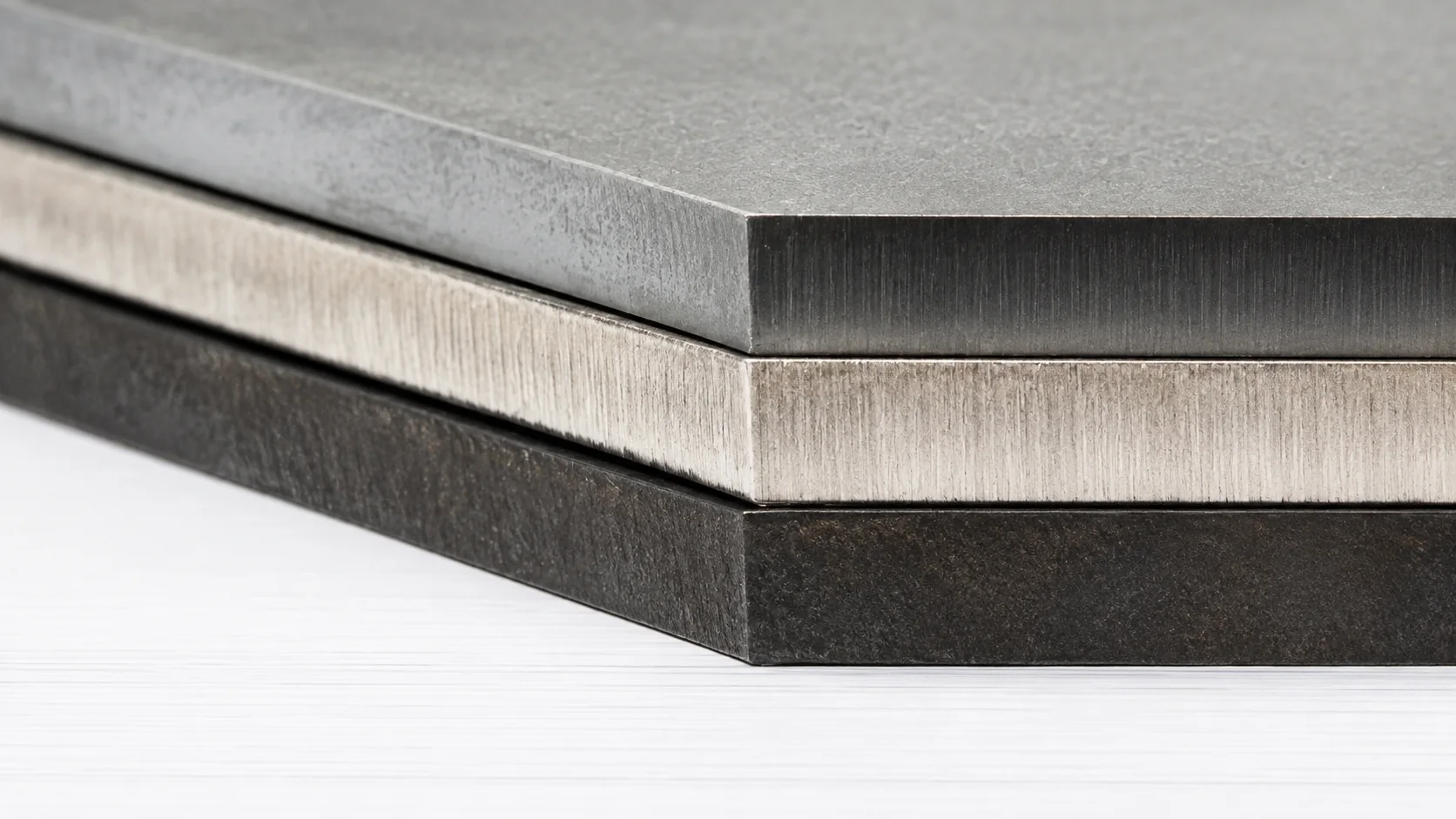
A laser-cut part can be dimensionally excellent and still need weld-zone preparation. Gas choice changes oxidation, color, dross behavior, and the work needed before welding or coating.
Representative cut-edge appearance. Actual edge condition varies with alloy, thickness, machine, gas, power, focus, and parameter set.
Cut process
Typical edge condition
Before welding
Design / drawing note
Oxygen / flame cutting
Reactive cutting supports speed in mild steel but leaves an oxidized edge.
Remove oxide, dross, coating, oil, and contamination in the weld zone as required by the WPS.
If edge chemistry matters, call out preparation or request a different cut process instead of relying on appearance.
Nitrogen / fusion cutting
Inert gas shields the kerf and produces an oxide-free edge when the process is in control.
Inspect for dross and burr; clean oils, films, moisture, and handling contamination. Follow material-specific oxide prep.
Useful when an oxide-free edge reduces downstream preparation, but it does not replace a cleaning requirement.
Mixed-gas cutting
A tuned oxygen/nitrogen mixture can balance speed, burr, and edge quality.
Treat preparation as process- and material-specific. Verify the actual edge against the approved weld plan.
Do not write “mixed gas” as a universal weld-quality guarantee; state the required edge/result.
Compressed air
Economical for some applications; edge oxidation and color vary by alloy and settings.
Assume the weld zone requires evaluation and cleaning unless the qualified procedure says otherwise.
Use only when the downstream welding and finish requirements accept the resulting edge.
Clean means more than “looks bright.”
Remove what the process and material require: loose dross, oxide or scale, moisture, oil, paint, powder coat, adhesive residue, marker, and cross-contamination. Use dedicated tools for aluminum and stainless where required, and protect cleaned surfaces from recontamination.
04 / Design for a controllable process
Make the joint repeatable, reachable, and inspectable.
Laser precision is most valuable when it supports the qualified joint—not when tight geometry prevents torch access, traps contamination, or creates excessive restraint.
A / ACCESS
Model the torch envelope
Confirm gun, cup/nozzle, electrode, travel angle, filler access, line of sight, and welder hand position. A CAD-visible seam can still be physically unreachable.
B / FIT-UP
Dimension the qualified joint
Root opening, land, bevel, mismatch, and alignment should match the WPS and realistic cut/form tolerances. Do not invent a universal “perfect gap.”
C / CLEARANCE
Protect nearby features
Keep holes, threads, press-fit hardware, seals, precision datums, bend lines, and cosmetic faces outside the heat/spatter zone unless the process plan protects them.
D / FIXTURING
Use tabs intentionally
Tabs and slots can locate parts, but an interference fit may hold the joint open or create restraint. Add assembly clearance and a removal/finish plan where needed.
E / HEAT
Balance the weld layout
When engineering permits, use symmetry, shorter segments, alternating locations, and a planned sequence to limit accumulated shrinkage and angular pull.
F / INSPECTION
Leave a way to verify
Give inspectors light, line of sight, gauge access, and access for any required PT, MT, UT, RT, leak, or dimensional examination.
Put design intent on the drawing.
Identify the weld symbol, joint detail, applicable standard, critical-to-function dimensions, finish/masking, inspection requirement, and any required domestic material or mill certification. Let the qualified welding documentation control variables that do not belong in the CAD geometry.
05 / Material-specific cautions
The alloy decides what is possible.
“Aluminum,” “steel,” and “stainless” are families, not procedures. Confirm the exact grade, temper, filler, service, and applicable welding code before release.
Commonly weldable
Mild steel
Generally forgiving, but mill scale, oil, rust, oxygen-cut oxide, coating, hydrogen control, restraint, and service conditions still matter.
Shielding critical
Stainless steel
Control contamination and heat tint; some joints require back purging. Preserve corrosion performance through the specified cleaning/passivation route.
Coating hazard
Galvanized / coated
Coatings affect arc stability and fume exposure. Follow the approved removal, ventilation, respiratory protection, restoration, and safety plan.
Good candidate
5052 aluminum
A widely welded 5xxx sheet alloy. Filler selection, oxide removal, cleanliness, heat input, and the exact magnesium content/service still require qualified guidance.
HAZ strength loss
6061-T6 aluminum
Commonly welded, but welding changes the T6 temper in the heat-affected zone. Design strength must use the applicable welded allowables—not the unwelded T6 value.
Do not assume weldable
7075 aluminum
Generally unsuitable for conventional arc welding because of solidification-cracking and stress-corrosion risks. Use another joining route or qualified engineering/process authority.
Start with the approved acceptance criteria. Select the examination method for the material, joint, likely discontinuity orientation, access, risk, and governing code.
VT
Visual testing
Surface condition, profile, size, alignment, cracks, porosity, undercut, overlap, spatter, and dimensional clues. Often performed before, during, and after welding.
PT
Liquid penetrant
Surface-breaking indications in nonporous materials. Cleaning and dwell/development steps are procedure-controlled.
MT
Magnetic particle
Surface and near-surface indications in ferromagnetic materials only; not a method for aluminum or austenitic stainless steel.
UT
Ultrasonic testing
Internal indications using sound. Joint geometry, thickness, surface condition, orientation, equipment, and qualified technique affect suitability.
RT
Radiographic testing
Volumetric examination using ionizing radiation. Requires controlled access, qualified personnel, and a technique appropriate to the joint.
No web guide can accept or reject a production weld.
Use the applicable code/specification and qualified inspection personnel. Crack-like indications, safety-critical service, pressure boundaries, lifting points, structural connections, and fatigue-loaded parts deserve immediate escalation.
07 / Release checklist
Before you upload the weldment.
01
Material is exact.Grade, temper, thickness, coating, filler compatibility, and certification requirements are known.
02
The governing requirement is named.Drawing, code, contract notes, WPS, weld symbols, acceptance criteria, and inspection level agree.
03
The cut edge is intentional.Assist gas, oxide/dross expectation, burr direction, edge preparation, and contamination control fit the welding plan.
04
Fit-up has tolerances.Root gap, bevel/land, mismatch, tabs/slots, bend variation, and assembly clearance are dimensioned realistically.
05
The welder can reach it.Torch, filler, backing, tack, cleaning, interpass, and repair access have been checked in 3D.
06
Heat-sensitive features are protected.Threads, hardware, bends, seals, datums, finishes, and cosmetic surfaces have adequate clearance or protection.
07
Distortion has a plan.Joint symmetry, weld sequence, fixture datums, restraint, preset, machining allowance, and final tolerance strategy are coordinated.
08
Inspection access exists.The required surfaces and volumes can be cleaned, illuminated, gauged, examined, and documented.
08 / Frequently asked questions
Welding-defect FAQs.
What is the difference between a discontinuity and a defect?
A discontinuity is an interruption in the expected structure of the weldment. It is a defect only when it does not meet the acceptance criteria that govern the job.
Should an oxygen-cut laser edge be prepared before welding?
Oxygen cutting leaves an oxide-bearing edge on mild steel. Prepare the weld zone as required by the WPS—commonly including removal of oxide, dross, oil, coating, moisture, and other contamination.
Does nitrogen cutting eliminate all weld preparation?
No. Nitrogen fusion cutting can produce an oxide-free edge, but the joint still needs inspection and material-appropriate cleaning. Burr, dross, oil, film, oxide elsewhere on the joint, and handling contamination can still matter.
Can 7075 aluminum be arc welded?
7075 is generally considered unsuitable for conventional arc welding. Its cracking and stress-corrosion risks can cause premature failure. Do not use it in a welded design without qualified engineering and process authority.
Can visual inspection prove a weld is acceptable?
Visual testing is the foundational first step, but acceptance depends on the applicable requirements. Some jobs also require PT, MT, UT, RT, destructive testing, leak testing, or other examination.
Upload your laser-cut and bent component files for an instant quote. Include the alloy, edge-preparation needs, critical fit-up dimensions, certifications, and drawing requirements that matter to the finished weldment.