The ACB Laser on Our TRUMPF 5170
A Xeon NC Machine Guide on Automatically Controlled Bending — how our press brake measures the real angle of your part while it is still under load, and corrects springback before the ram ever retracts.
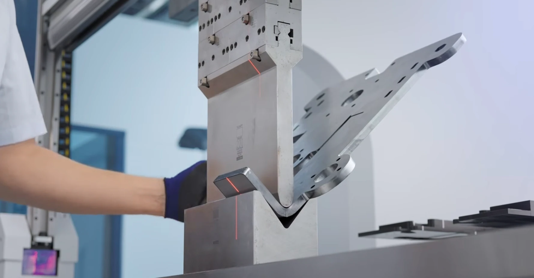
The two red lines you can see running across the flanges are the ACB laser. They are not alignment markers — they are the measurement itself, being read continuously while the punch is still driving the sheet into the die.
ACB stands for Automatically Controlled Bending. It is a closed-loop, non-contact angle measurement system on our TRUMPF TruBend 5170 press brake. Instead of bending to a calculated ram depth and hoping the sheet cooperates, the machine watches the actual angle of your part forming in real time and adjusts the stroke until the angle is correct.
That distinction matters more than it sounds. A conventional press brake is an open-loop machine: the control computes how deep the punch must travel to produce a 90° bend given a material, a thickness, and a V-opening, then it drives to that depth. If the sheet is a little harder than the datasheet says, or the coil came off the mill with a slightly different temper, or the grain is running the wrong way through the bend, the part comes out at 88.5° or 91.2° and nobody knows until it is measured with a protractor.
ACB removes the guess. The laser measures, the control corrects, and the part leaves the tooling at the angle that was programmed — on the first stroke, not the fourth.
The Problem It Solves: Springback
When a punch drives sheet metal into a V-die, two things happen at once. The material yields and takes a permanent set — that is the bend. But it is also elastically strained, and elastic strain is recoverable. The instant the punch releases pressure, the outer fibers relax and pull the flanges back open by some amount. That recovery is springback.
Springback is not a small correction, and it is not a constant. It scales with:
- Yield strength. The higher the yield, the more elastic energy is stored, and the more the part opens back up. 6061-T6 springs back dramatically more than 5052-H32 at identical thickness and tooling.
- Work hardening behavior. 304 stainless hardens aggressively as it forms. The material at the end of the stroke is not the material you started the stroke with.
- Ratio of bend radius to thickness. A large inside radius relative to material thickness stores proportionally more elastic strain and springs back harder than a tight radius.
- Actual thickness, not nominal. Mill tolerance on 0.125″ aluminum is real. A sheet running at the thin end of tolerance bends differently than one at the thick end — in the same lot.
- Grain direction. A bend running with the rolling direction behaves differently than one running across it, on the same blank.
Traditional shops handle this by over-bending: form past the target angle by an empirically derived amount so the part springs back to where you wanted it. That works, but the compensation value has to come from somewhere — and where it comes from is test bends. Set up, bend a coupon, measure it, adjust the program, bend another, measure again, and repeat until the angle lands. Every test bend is scrap material and setup time on a machine that should be making parts.
How the Measurement Actually Works
The ACB system projects a laser line onto the sheet on each side of the bend and optically reads where that line falls. Because the sensors know their own position and orientation relative to the tooling, the deviation of each projected line tells the control exactly how far that flange has rotated away from flat.
The geometry is straightforward. Each flange is measured independently — call those deviations β and γ — and the included angle of the bend follows directly:
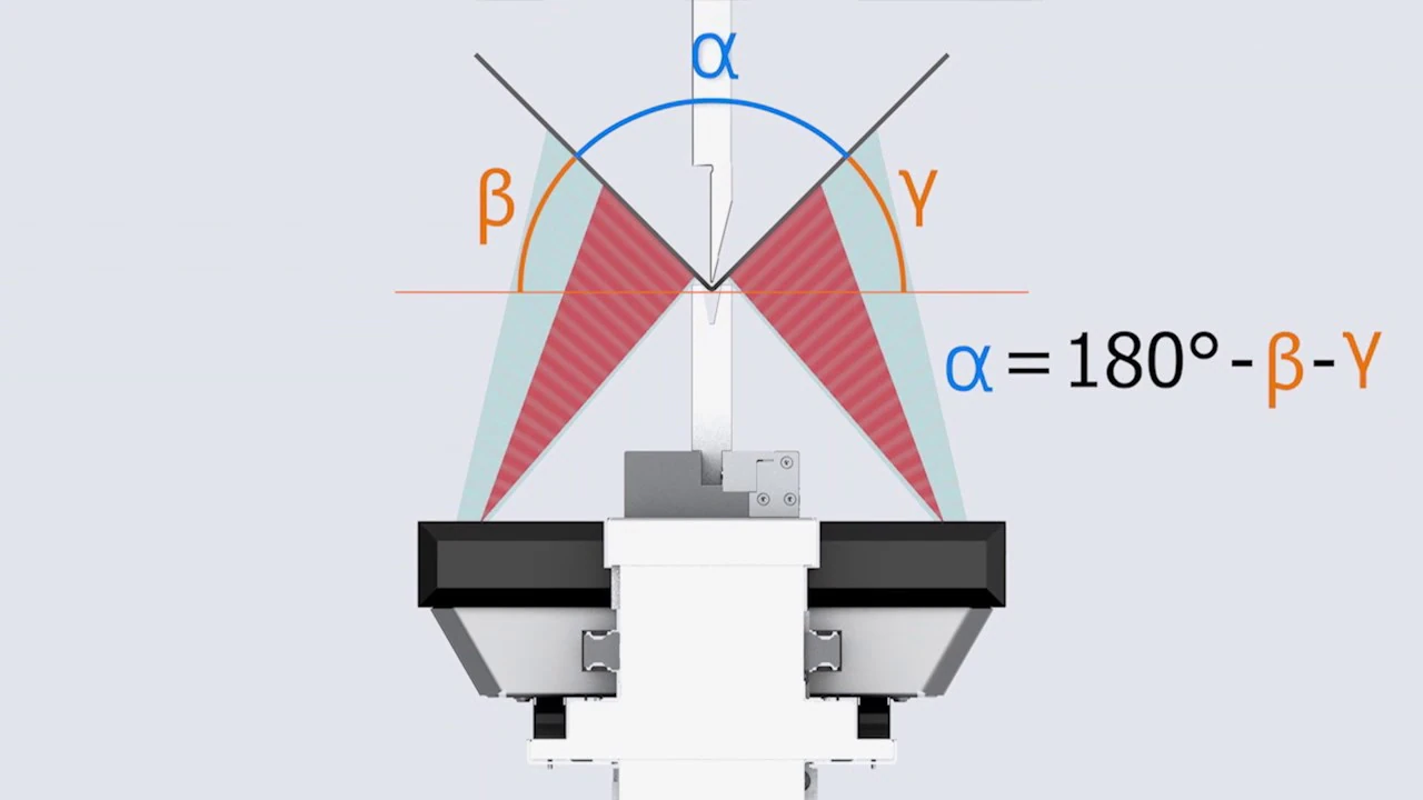
Each flange is measured on its own. The included bend angle α is derived from both measurements, not assumed from ram position.
Measuring both flanges separately rather than inferring one angle from ram depth has a consequence worth spelling out: the system sees asymmetry. If one leg is rotating faster than the other — because the blank is not centered, because the flange lengths differ, because there is a cut-out weakening one side — the control knows. A depth-only machine cannot distinguish that case from a symmetric bend at all.
Non-contact, and why that matters
Nothing touches the workpiece to take the measurement. There is no probe, no feeler, no mechanical arm riding the flange. On cosmetic parts — anodized aluminum, brushed stainless, pre-finished sheet, anything that is going to be visible on a finished product — a contact measuring device is a scratch waiting to happen. An optical measurement leaves no mark at all.
It also means measurement costs no cycle time. The laser is reading during the stroke that is already happening, not in an added step after it.
Correction Inside the Stroke
This is the part that separates ACB from simply inspecting a part after the fact. The correction happens while the punch is still down.
- The ram descends and the bend begins to form. The backgauge has staged the blank; the punch drives the sheet into the V-opening. Nothing unusual so far.
- The lasers begin reading both flanges continuously. As the metal wraps the punch radius, the projected lines move. The control is now tracking a live angle value, not a predicted one.
- The machine performs a controlled partial release and reads the elastic recovery. Before committing, the system relieves pressure slightly and measures how much the flanges relax. That relaxation is the springback of this specific sheet — measured, not estimated from a table.
- The control computes the required over-bend from the measured recovery. Now it knows exactly how much further it needs to push this particular piece of metal so that when it does let go, the part relaxes to the programmed angle.
- The stroke is extended to the corrected depth and released. The part springs back to target. The angle is right on the first part.
- The correction is carried into the rest of the run. The learned value informs subsequent strokes, and the lasers keep measuring — so if the material drifts partway through a batch, the compensation drifts with it.
The TRUMPF 5170 Bending Cell
ACB does not work in isolation. It is one of several closed-loop systems on the machine, and the accuracy you get out of the cell is the product of all of them working together. The backgauge has to place the blank correctly before the laser has anything meaningful to measure.
| System | What it does |
|---|---|
| ACB Laser | Non-contact optical angle measurement on both flanges, read continuously during the stroke. Springback is measured per part and compensated inside the same stroke. |
| 6-Axis Backgauge | Fully independent X1/X2, R1/R2 and Z1/Z2 positioning. Asymmetric parts, tapered flanges and progressive multi-step bends stage repeatably without custom fixtures or manual stops. |
| I-Axis (Lower Die Shift) | Programmable lateral displacement of the lower tool. Allows transitions from standard V-bending into hemming and offset joggles without a manual tooling change. |
| Angle Tolerance | ±0.5° standard, subject to flange length, material grain direction and part geometry. |
| Bend Angle Range | 30° to 135° air bending on a five-die TRUMPF set, V-opening selected at roughly 8× material thickness. |
| Max Bend Length | Up to 120″, depending on tonnage demand for the material and thickness. |
Because the tooling set, V-openings and resulting inside radii are known quantities in our system, the bend deduction and K-factor values we program from are derived from the tooling we actually run — not generic handbook numbers. You can pull those exact values for any material and gauge we stock from the Bending Ontology & Material Specs lookup, or see the punch and die assignments per gauge in the Press Brake Tooling Library.
What This Means for Your Part
The technology is interesting, but what you care about is what shows up in the box. Four things change.
Where you feel it most
- Enclosures and chassis. Four-bend U-channels and wrap boxes where accumulated angle error decides whether the lid actually sits flat and the fasteners line up.
- Weldments and assemblies. Parts that have to mate with other parts. Angle error at the brake becomes gap and misalignment at the weld fixture.
- Hard-tempered alloys. 6061-T6 and 304 stainless, where springback is large and highly variable. This is exactly the case where table-based compensation is least reliable and measured compensation wins by the most.
- Prototype quantities. One part. There is no opportunity to converge on the right compensation through iteration when the run length is one, so measuring it on the part itself is the only approach that works.
- Repeat orders. The parts you order next quarter match the parts you approved this quarter, even though the material came from a different coil.
Where ACB Can't Reach
No process is unconditional, and it is more useful to tell you the boundaries than to pretend there aren't any.
- Very short flanges. The laser needs enough flat flange surface to project onto and read. A leg near the minimum formed flange height for its gauge may not present enough surface for a reliable measurement, and the bend falls back to conventional depth control. Keeping flanges at or above roughly 4× material thickness is good practice for this reason as well as formability.
- Obstructed measurement lines. Features that block the optical path across the flange — a large cut-out right at the measurement zone, a previously formed flange folded into the way, an already-inserted piece of hardware — can interfere with the reading.
- Geometry that cannot be measured on both sides. Some closed or deeply nested forms simply do not present two readable flanges to the sensors at the moment of the bend.
- It measures angle, not everything else. ACB controls the bend angle. It does not correct a flat pattern that was developed with the wrong bend deduction, it does not fix a hole placed inside the bend affected zone, and it does not prevent outer-fiber cracking on a radius that is too tight for the alloy. Those are design-side problems and have to be solved on the flat.
- Cracking and marking are separate concerns. A correct angle on a cracked flange is still a scrap part. Material selection and radius specification still matter.
Designing to Take Advantage of It
You do not have to do anything special to benefit from ACB — it runs on every job that can use it. But a few habits let you get more out of it and avoid the cases where it can't help.
1. Give your flanges room to be measured
Flanges at or above 4× material thickness both form more predictably and give the laser a clean surface to read. Where a design calls for a very short leg, expect that bend to be less tightly controlled than the rest of the part, and tolerance it accordingly.
2. Specify the angle tolerance you actually need
If a bend has to be tighter than ±0.5°, say so on the drawing rather than assuming. Tighter is sometimes achievable on favorable geometry, but only if we know it is a requirement before programming. Conversely, if ±2° is genuinely fine for a bracket nobody will measure, saying so gives us room to optimize.
3. Keep cut-outs clear of the bend zone
Features crowding the bend line cause two problems at once: they distort in the bend affected zone, and they can obstruct the measurement. Holding standard BAZ clearances solves both.
4. Specify your inside radius
ACB controls the angle. It does not control the radius — that comes from the punch tip and V-opening. If your part has a radius requirement, put it on the drawing so the correct tooling is selected rather than defaulted.
5. Call out grain direction on critical bends
ACB compensates for the springback difference between with-grain and across-grain bends automatically, so the angle will be right either way. But cracking risk still depends on orientation. If a bend is severe for the alloy, note "bend perpendicular to grain" on the drawing.
6. Trust the flat pattern to us if you're unsure
Send a 3D STEP file of the formed part rather than a flat DXF you developed yourself. We will develop the flat using the bend deduction values for the exact tooling that will run the job, which eliminates a whole category of dimensional error that no amount of angle measurement can rescue.