Home/Calculators/DFM Lookup

Design for Manufacturability
& Error Code Lookup

Got a warning on your instant quote? Type the code below. Every rule our preflight can raise is documented here — what it means, why the process behaves that way, and exactly how to fix it in CAD.

Press / to search  ·  Esc to clear
Codes documented
DFM rules
Categories
<60s
From code to fix
Severity

No rule matches that

Check the code digits, or try a keyword like flange, countersink, DXF, or powder coating. If the code came from your quote and is not here, send it to us and we will add it.

Email us the code
// 01 — CAD & DXF Files · 32 codes

CAD & DXF Files

File read errors, entity warnings, and contour problems found before geometry is even analyzed.

What the quote app saysCannot read STEP file.

// What it means

The upload finished but the STEP could not be parsed into geometry. The file is truncated, corrupted, compressed, or is not actually a STEP file despite the extension.

// Why it happens

STEP is a text-based exchange format with a strict header and data section. Cloud exports that fail partway, files renamed from another format, and files zipped by the browser all produce a body the kernel cannot open.

// How to fix it
  1. Re-export from CAD as AP203 or AP214 STEP and upload the fresh file.
  2. Confirm the file opens in your own CAD before re-uploading.
  3. Do not rename a .stl, .sldprt, or .ipt to .step — the extension does not convert the format.
  4. If the file is over 100 MB, suppress unused bodies and export only the part being quoted.
Diagram coming soon
Video walkthrough Coming soon
What the quote app saysCould not read DXF file

// What it means

The DXF header or entity table is malformed, so no geometry could be loaded at all.

// Why it happens

Many drawing tools write non-standard or very old DXF revisions. Binary DXF, DWG renamed to DXF, and files exported from illustration software with clipping groups are the usual causes.

// How to fix it
  1. Export as ASCII DXF, R2013 or later, from your CAD package.
  2. If the drawing came from Illustrator or Inkscape, re-export as DXF with text converted to paths and no clipping masks.
  3. As a fallback, upload a STEP of the flat part instead — the engine can flatten it for you.
Diagram coming soon
Video walkthrough Coming soon
// Related CAD file prep guide →

What the quote app saysThis file is not recognized.

// What it means

The file type is not one the quote engine accepts for this process.

// Why it happens

Online pricing needs exact geometry. Mesh and picture formats describe a surface approximation or pixels, not the contours and thickness the engine needs to nest and price a part.

// How to fix it
  1. For sheet metal: upload STEP (.step / .stp) for 3D parts, or DXF for flat parts.
  2. For 3D printing: upload STL or STEP.
  3. PDF, JPG, PNG, and screenshots cannot be quoted automatically — send them to quote@xeonnc.com for a manual review.
Diagram coming soon
Video walkthrough Coming soon
// Related How instant quoting works →

What the quote app saysSTEP files does not contain any solid objects.

// What it means

The STEP opened, but it holds only surfaces, curves, or reference geometry — there is no closed solid to measure a thickness from.

// Why it happens

Sheet metal pricing derives thickness, flat pattern, and cut length from a watertight solid. Surface bodies have no volume, so none of those can be computed.

// How to fix it
  1. Thicken or knit your surfaces into a solid body before exporting.
  2. In the export dialog, make sure solids are included and that sketches, planes, and construction curves are excluded.
  3. If the part really is a flat 2D outline, export a DXF instead and select the thickness in the quote app.
Diagram coming soon
Video walkthrough Coming soon
// Related CAD file prep guide →

What the quote app saysCAD assembly contains non-solid components.

// What it means

You uploaded an assembly, and at least one component in it is a surface body, a sketch, or an empty reference part.

// Why it happens

The engine prices each component individually. Anything without volume breaks that loop, so the whole assembly is rejected rather than silently skipped.

// How to fix it
  1. Delete reference geometry, dummy parts, and imported fixtures from the assembly before exporting.
  2. Convert any surface component into a solid.
  3. Simplest path: export each manufactured part as its own STEP and upload them together.
Diagram coming soon
Video walkthrough Coming soon
// Related CAD file prep guide →

What the quote app saysThe file contains an open contour.

// What it means

One or more cut paths do not close back on themselves. There is a gap somewhere in the outline or in an internal cutout.

// Why it happens

A laser follows closed loops. An open contour has no inside and no outside, so the machine cannot decide what to keep and what to drop — and the nest cannot compute part area.

SpecEvery cut path must be a closed loop — outline and all internal features.
// How to fix it
  1. Run your CAD tool's "close gaps" or "join" command on the outline, then on every internal cutout.
  2. Look for gaps smaller than 0.001″ at line endpoints — these are invisible on screen but still open the loop.
  3. Delete duplicate segments stacked on top of each other; they often prevent a clean join.
  4. Re-export and confirm the outline reports as a single closed polyline.
Diagram coming soon
Video walkthrough Coming soon
// Related CAD file prep guide →

What the quote app saysFlat pattern contains self-overlapping zones. Contours and bendlines must not touch or intersect themselves and each other in the unfolded part.

// What it means

When the part is unfolded, two areas of material land on top of each other, or a cut line crosses a bend line.

// Why it happens

The flat blank is what actually gets cut. If the unfolded outline overlaps itself, the blank is physically impossible — the same piece of steel would have to be in two places. Cut lines crossing bend lines mean the brake would be bending across an open slot.

// How to fix it
  1. Unfold the part in your own CAD and look at the flat pattern — the overlap will be obvious there.
  2. Usually caused by adjacent flanges that collide when flattened. Add a corner relief or shorten one flange.
  3. Keep cutouts fully on one side of a bend line, or move them clear of the bend zone entirely.
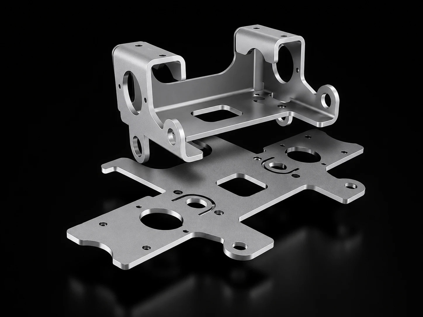
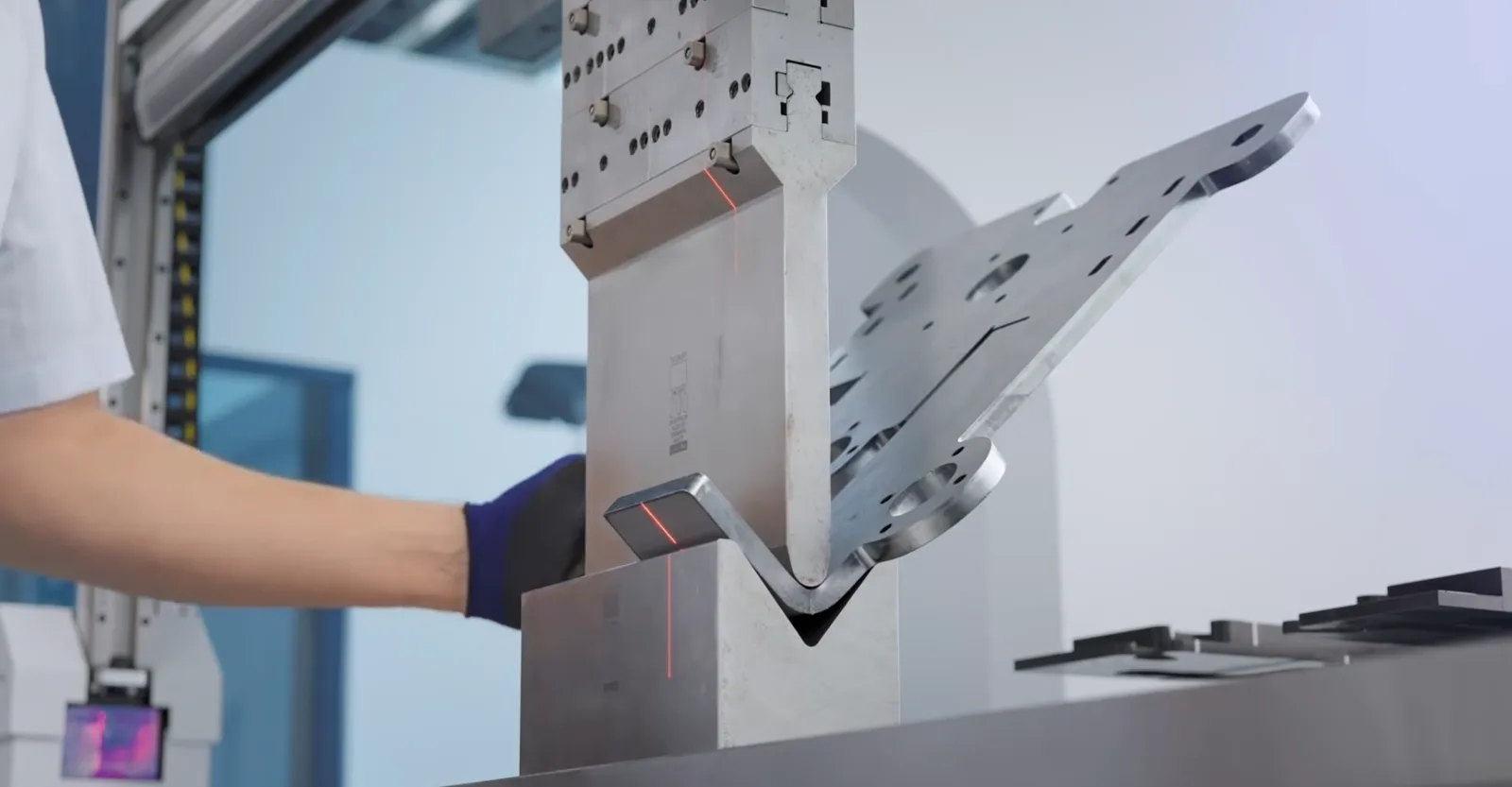
Flat laser-cut blank next to the same part after forming on the press brake
Every bent part starts as a flat blank — the engine has to unfold your solid to price the cut.
Video walkthrough Coming soon
// Related Sheet metal design guide →

What the quote app saysA deviation in the perpendicularly of the outer contour has been detected. Contour will be cut perpendicular.

// What it means

Part of the outside edge is drafted, chamfered, or angled through the thickness. A flat-sheet laser cuts square to the surface, so that angle will be removed.

// Why it happens

A 2D fiber laser cuts straight down. Any bevel modelled on the perimeter cannot be produced on the cutting table — the engine flattens it to a perpendicular edge and prices it that way.

// How to fix it
  1. Accept it if the bevel was cosmetic — the part ships with a square edge.
  2. If the bevel is functional, remove it from the model and call it out as a secondary machining operation.
  3. Edge breaks and deburring are available as a finishing option instead of a modelled chamfer.
Diagram coming soon
Video walkthrough Coming soon
// Related Deburring & edge break →

What the quote app saysA deviation in the perpendicularly of the inner contour has been detected. Contour will be cut perpendicular.

// What it means

An internal cutout carries a taper, draft, or chamfer through the thickness. It will be cut straight through instead.

// Why it happens

Same reason as the outer contour: the laser head cuts normal to the sheet. Tapered holes have to be produced by drilling, countersinking, or machining.

// How to fix it
  1. If you need a tapered hole for a flat-head screw, specify it as a countersink instead of modelling the taper.
  2. Remove the draft from the model so the quote matches what will be produced.
  3. For true tapered bores, request post-process machining.
Diagram coming soon
Video walkthrough Coming soon
// Related Countersink guide →

What the quote app saysThe passed file contains non-millimeter units

// What it means

The drawing header declares units other than millimeters — usually inches, or no unit at all.

// Why it happens

DXF stores raw numbers plus a units flag. If the flag disagrees with what you drew, a 10″ part can arrive as a 10 mm part. The engine flags it rather than guessing and cutting a part 25× the wrong size.

SpecPreferred DXF unit: millimeters.
// How to fix it
  1. Set your drawing units to millimeters and re-export, or
  2. Confirm the scale shown in the quote app preview against your intended overall dimensions before adding to cart.
  3. Always check the bounding box the app reports — it is the fastest catch for a units mistake.
Diagram coming soon
Video walkthrough Coming soon
// Related CAD file prep guide →

What the quote app saysNot a 2D object

// What it means

The DXF holds geometry at more than one Z height, so it is not a flat profile.

// Why it happens

A DXF for laser cutting must be a single flat outline in one plane. 3D wireframe exports, isometric views, and folded models saved as DXF all carry Z values the cutter cannot use.

// How to fix it
  1. Export the flat pattern view only, not a 3D or isometric view.
  2. Flatten all geometry to Z = 0 before export.
  3. If the part is bent, upload the STEP instead and let the engine unfold it.
Diagram coming soon
Video walkthrough Coming soon
// Related CAD file prep guide →

What the quote app saysSpline entities

// What it means

The drawing contains splines. They are converted to line and arc segments before cutting, which can shift the contour slightly.

// Why it happens

CNC controllers run on lines and arcs. Every spline gets approximated, and the tolerance of that approximation is set by the converter — not by you.

// How to fix it
  1. Convert splines to polylines or arcs in CAD, where you control the chord tolerance.
  2. Use a tight tolerance (0.001″ / 0.025 mm) so the cut path matches your intent.
  3. For a true circle or arc, redraw it as a circle or arc entity rather than a spline.
Diagram coming soon
Video walkthrough Coming soon
// Related CAD file prep guide →

What the quote app saysNon-continuous lines that are not in price calculation

// What it means

Dashed, dotted, hidden, or center-line entities were found. They were excluded from the cut path and from pricing.

// Why it happens

By convention non-continuous line types are annotation — center marks, hidden edges, bend indicators. Cutting them would slice the part apart, so the engine drops them.

// How to fix it
  1. If those lines were meant to be cut, change them to a continuous line type and re-export.
  2. If they were annotation, no action is needed — the part will be cut correctly.
  3. Keep annotation on its own layer so it is easy to purge before export.
Diagram coming soon
Video walkthrough Coming soon
// Related CAD file prep guide →

What the quote app saysBYBLOCK or BYLAYER entities in notContinuous array

// What it means

Some entities inherit their line type from a block or layer that resolves to a non-continuous style, so their intent is ambiguous.

// Why it happens

Inherited properties only resolve if the parent block and layer definitions survive the export. When they do not, the engine cannot tell a cut line from an annotation line.

// How to fix it
  1. Explode all blocks before exporting so every entity carries its own properties.
  2. Set cut geometry explicitly to a continuous line type rather than BYLAYER.
  3. Purge unused layers and blocks, then re-export.
Diagram coming soon
Video walkthrough Coming soon
// Related CAD file prep guide →

What the quote app saysDimension entities

// What it means

Drawing dimensions were found in the file. They are ignored for cutting.

// Why it happens

A cut file is geometry, not a drawing. Dimension entities carry extension lines and arrowheads that would otherwise be read as contours.

// How to fix it
  1. Delete all dimensions from the DXF before export — send the dimensioned drawing as a separate PDF if you need it on record.
  2. Keep dimensions on a dedicated layer so a single purge removes them.
Diagram coming soon
Video walkthrough Coming soon
// Related Dimensioning formed parts →

What the quote app saysHatch entities

// What it means

Hatch or fill patterns are present. They are not cut, but they can confuse contour detection and area calculation.

// Why it happens

A hatch is hundreds of short parallel lines. If the engine treats them as geometry, part area and cut length both come out badly wrong.

// How to fix it
  1. Delete all hatching before export.
  2. If you were using hatch to indicate an area to be removed, replace it with a proper closed cutout contour.
Diagram coming soon
Video walkthrough Coming soon
// Related All guides →

What the quote app saysPoint entities

// What it means

Bare point entities exist in the drawing. They produce no cut.

// Why it happens

Points are often left behind as construction markers or hole centers. They carry no diameter, so the engine cannot turn them into holes.

// How to fix it
  1. If a point was marking a hole location, replace it with an actual circle at the correct diameter.
  2. Otherwise delete the points before export.
Diagram coming soon
Video walkthrough Coming soon
// Related All guides →

What the quote app saysText entities

// What it means

Live text objects are in the file. Text is not cut or engraved unless you order engraving and the text is converted to geometry.

// Why it happens

Text renders from a font at display time. Without the font outline converted to closed paths, there is nothing for the machine to follow.

// How to fix it
  1. Delete notes and title blocks from the cut file.
  2. If the text must be cut or engraved, convert it to outlines / polylines first, then confirm every letter is a closed contour.
  3. Closed counters (the holes in A, O, R) must be present or the letters will cut out as solid blobs.
Diagram coming soon
Video walkthrough Coming soon
// Related All guides →

What the quote app saysCould not find used font in the system

// What it means

Text in the DXF references a font that is not installed on the processing server, so it cannot be rendered or converted.

// Why it happens

DXF stores a font name, not the font itself. Anything non-standard — a custom shop font, an SHX style — will not resolve elsewhere.

// How to fix it
  1. Convert all text to outlines before export. This removes font dependency completely.
  2. If text is only annotation, delete it from the cut file.
Diagram coming soon
Video walkthrough Coming soon
// Related All guides →

What the quote app saysLines or shapes are overlapping

// What it means

Duplicate geometry sits on top of itself, or two contours share the same path.

// Why it happens

Duplicates make the laser cut the same line twice. That doubles cut time, burns the edge on the second pass, and inflates the quoted price because cut length is counted twice.

// How to fix it
  1. Run an overkill / delete-duplicates command in your CAD before export.
  2. Watch for geometry copied and pasted in place — the most common source.
  3. Confirm the total entity count drops after the cleanup.
Diagram coming soon
Video walkthrough Coming soon
// Related CAD file prep guide →

What the quote app saysUnconnected lines in drawing

// What it means

Line endpoints that should meet are separated by a small gap, leaving a contour that never closes.

// Why it happens

Exports at coarse precision, or geometry drawn without snaps, leave micro-gaps of a few ten-thousandths of an inch. They look closed on screen but are open to the machine.

// How to fix it
  1. Use a join or gap-close command with a tolerance around 0.005″ (0.13 mm).
  2. Turn endpoint snapping on before drawing or editing contours.
  3. Verify the outline selects as one continuous entity after joining.
Diagram coming soon
Video walkthrough Coming soon
// Related CAD file prep guide →

What the quote app saysSome lines have too many connection points

// What it means

Three or more segments meet at a single point, so the contour branches and the engine cannot tell which path forms the outline.

// Why it happens

A valid cut contour is a simple loop: each endpoint joins exactly one other endpoint. Branching happens when construction lines are left in, or when a cutout shares an edge with the perimeter.

// How to fix it
  1. Delete leftover construction and centerline geometry.
  2. Separate any cutout that touches the outer profile — give it its own closed loop or merge it into the perimeter properly.
  3. Check for stray segments crossing the outline.
Diagram coming soon
Video walkthrough Coming soon
// Related All guides →

What the quote app saysLines under 0.2 mm

// What it means

Extremely short segments were found — shorter than the laser kerf itself.

// Why it happens

Below roughly 0.008″ (0.2 mm) a segment is narrower than the beam. The cutter cannot resolve it, and dense clusters of micro-segments slow the head to a crawl and overheat the material.

SpecMinimum useful segment length ≈ 0.008″ (0.2 mm).
// How to fix it
  1. Clean up the contour: replace clusters of micro-segments with a single line or arc.
  2. Increase the chord tolerance when converting splines so it stops generating slivers.
  3. Round out micro-features that are below the process resolution anyway.
Diagram coming soon
Video walkthrough Coming soon
// Related Kerf & beam width guide →

What the quote app saysShapes are too close together

// What it means

Two contours leave a web of material between them that is too thin to survive cutting.

// Why it happens

The kerf removes material from both sides. A thin web loses rigidity, heats up on the second pass, and warps or burns through — taking both features out of tolerance.

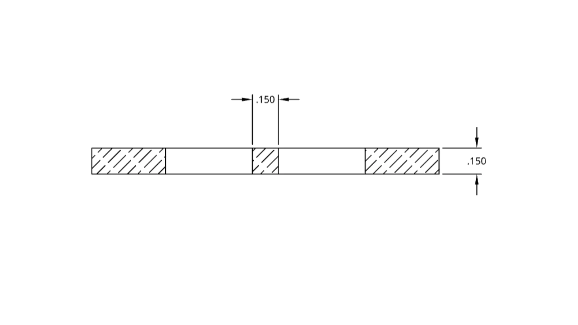
SpecMin. feature-to-feature and feature-to-edge = max(0.150″, 2 × thickness)
// How to fix it
  1. Keep at least 0.150″ (3.8 mm), or 2× material thickness — whichever is larger — between any two cut features.
  2. Apply the same minimum from any feature to the outside edge of the part.
  3. For dense hole patterns and ventilation grilles, send the pattern for engineering review before finalizing.
Sheet cross-section showing 0.150 inch minimum hole-to-hole and hole-to-edge spacing with hatched danger zones
Webs thinner than 0.150″ (or 2T) overheat during the second cut and distort.
Video walkthrough Coming soon
// Related Minimum hole spacing rules →

What the quote app saysCould not build area of contour face · Filled contour is not valid · Untrustworthy filled area · Untrustworthy total area · Could not check contours hierarchy · Oriented bounding box is not valid

// What it means

The engine loaded your geometry but could not reliably work out which loops are outlines and which are cutouts, so part area and bounding box are suspect.

// Why it happens

Area and nesting depend on a clean inside/outside hierarchy. Self-intersecting loops, duplicated outlines, and open contours all break that test — and material cost is computed from area, so an untrustworthy result is flagged rather than quoted.

// How to fix it
  1. Close every contour and delete duplicates, then re-export.
  2. Make sure the outer profile is a single loop with all cutouts fully inside it.
  3. Remove any geometry that sits outside the part outline — stray marks push the bounding box out.
  4. If it still fails, upload a STEP of the flat part instead.
Diagram coming soon
Video walkthrough Coming soon
// Related CAD file prep guide →

What the quote app saysCould not find any feasible part

// What it means

The file loaded, but nothing in it forms a manufacturable part outline.

// Why it happens

Usually the drawing holds only annotation, a title block, or geometry that never closes into a profile.

// How to fix it
  1. Confirm the cut geometry is actually in the file and not on a frozen or off layer.
  2. Delete the border and title block, leaving only part geometry.
  3. Re-export just the part, at 1:1 scale, with all layers visible.
Diagram coming soon
Video walkthrough Coming soon
// Related CAD file prep guide →
// 02 — Part Recognition · 16 codes

Part Recognition

The engine could not classify, unfold, or trust the solid model you uploaded.

What the quote app saysThis is not a sheet metal part.

// What it means

The solid does not have the constant-thickness, two-parallel-faces signature the engine looks for in a sheet metal body.

// Why it happens

Sheet metal pricing works by finding two large parallel faces separated by a constant thickness, then unfolding the bends between them. Machined blocks, castings, and modelled weldments do not fit that pattern.

// How to fix it
  1. If the part really is sheet metal, model it with a sheet metal feature set so thickness stays constant everywhere.
  2. Remove machined details — chamfers on the thickness faces, varying wall thickness, and solid bosses all break recognition.
  3. If it is a machined part, quote it as CNC machining instead of sheet metal.
Flat laser-cut blank next to the same part after forming on the press brake
Every bent part starts as a flat blank — the engine has to unfold your solid to price the cut.
Video walkthrough Coming soon

What the quote app saysNo calculable parts detected.

// What it means

Nothing in the upload could be turned into a priceable part.

// Why it happens

Either every body failed recognition, or the file contains only reference geometry and no manufactured component.

// How to fix it
  1. Open the file and confirm it contains the solid you expect.
  2. Export only the manufactured parts — leave out fixtures, fasteners, and reference bodies.
  3. Check each part individually to find which one is failing.
Diagram coming soon
Video walkthrough Coming soon
// Related All guides →

What the quote app saysUnrecognized part. · The body is unrecognized, though some features are.

// What it means

The engine identified some features but could not resolve the body into a complete, manufacturable sheet metal part.

// Why it happens

Partial recognition usually points at one bad region — a corner that will not unfold, an imported face with bad topology, or a feature that conflicts with the sheet metal model.

// How to fix it
  1. Rebuild the part using your CAD system's sheet metal environment rather than as a generic solid.
  2. Check corners where three faces meet — unmitered or overlapping corners are the usual culprit.
  3. Re-export as a fresh STEP from a rebuilt model rather than repairing the old export.
  4. If it still fails, send the file to quote@xeonnc.com — we will review it manually.
Diagram coming soon
Video walkthrough Coming soon
// Related Modelling perfect sheet metal →

What the quote app saysProfile with varying thicknesses have been detected. · Inconsistent material thickness detected.

// What it means

Different regions of the body measure different thicknesses, so the engine cannot choose a sheet gauge.

// Why it happens

A part is cut from one sheet of one gauge. Varying thickness means the model is not a true sheet metal part — or a machined pocket, embossed area, or modelling error has changed the wall locally.

SpecOne part = one constant thickness.
// How to fix it
  1. Measure the wall in several places in CAD and find the region that differs.
  2. Remove pockets, embosses, and local thinning — those are machining or forming operations, not laser + brake work.
  3. Rebuild from a single sheet metal base flange so thickness is driven by one parameter.
  4. If the design genuinely needs varying thickness, split it into separate parts to be joined, or quote it as CNC machining.
Diagram coming soon
Video walkthrough Coming soon
// Related Available gauges →

What the quote app saysThe body contains an isolated thickness face, which is not acceptable.

// What it means

A face on the edge of the sheet is not connected to the top and bottom faces the way a cut edge should be.

// Why it happens

Every edge face must run cleanly between the two sheet surfaces. Isolated edge faces come from bad boolean operations, imported geometry with healing errors, or a chamfer applied to the thickness.

// How to fix it
  1. Remove chamfers and fillets applied to the thickness (edge) faces — the laser cuts those edges square anyway.
  2. Run your CAD system's geometry check / heal command on the body.
  3. Rebuild the feature that created the edge rather than patching it.
Diagram coming soon
Video walkthrough Coming soon
// Related All guides →

What the quote app saysUnfolding failure.

// What it means

The part was recognized as sheet metal, but it could not be flattened into a blank.

// Why it happens

Unfolding fails when bends conflict — flanges that overlap when flattened, bends that run into each other, non-developable curved faces, or bends applied to an already-bent region.

// How to fix it
  1. Flatten the part in your own CAD. Whatever error it reports is the same one the engine hit.
  2. Add corner reliefs where two bends meet — this fixes most unfold failures.
  3. Replace any rolled or conical face with a true press brake bend; only developable surfaces can be flattened.
  4. Check that no bend radius is smaller than the material thickness.
Flat laser-cut blank next to the same part after forming on the press brake
Every bent part starts as a flat blank — the engine has to unfold your solid to price the cut.
Video walkthrough Coming soon

What the quote app saysUnknown body-level error. · The body has too large geometric tolerance.

// What it means

The solid has topology or precision problems: faces that do not quite meet, edges outside the kernel's tolerance, or a body that fails a validity check.

// Why it happens

STEP files carry a modelling tolerance. When a body was built or translated at coarse precision, faces can be several thousandths apart while still being reported as joined. Downstream operations then fail unpredictably.

// How to fix it
  1. Re-export the STEP with the tightest precision setting your CAD offers.
  2. Run a geometry check in CAD and repair any reported faults before exporting.
  3. Avoid round-tripping through multiple formats — export STEP directly from the native model.
Diagram coming soon
Video walkthrough Coming soon
// Related STEP export walkthrough →

What the quote app saysThis product design is technically not feasible.

// What it means

The combination of features cannot be produced on our line as modelled — the geometry passes individual checks but fails as a whole.

// Why it happens

Feasibility is a whole-part test: tooling has to physically reach every bend in sequence without the part colliding with the ram, the backgauge, or itself. Deep boxes, opposing flanges, and closed sections often fail here.

// How to fix it
  1. Look for a bend that would trap the tooling — a fully closed box or a flange that folds over another.
  2. Try changing bend order in your head: can each bend still be reached once the previous one exists?
  3. Split the part into two pieces joined by hardware or welding.
  4. Send it to quote@xeonnc.com — our engineering team can often suggest a small change that makes it buildable.
Diagram coming soon
Video walkthrough Coming soon

What the quote app saysFace maximization algorithm of kernel failed. · Face maximization algorithm of CAD kernel failed.

// What it means

The CAD kernel could not merge adjacent coplanar faces into single faces, so the part is described as many small fragments.

// Why it happens

Imported and translated bodies often arrive split into dozens of tiny coplanar faces. Recognition relies on finding two large parallel faces, so heavy fragmentation prevents it.

// How to fix it
  1. Re-export STEP from the native CAD model rather than from an imported or translated body.
  2. Run a "merge faces" / "simplify" operation before exporting.
  3. Avoid exporting from a mesh-converted solid — those always fragment.
Diagram coming soon
Video walkthrough Coming soon
// Related All guides →

What the quote app saysNon-closed contours in some CAD faces.

// What it means

One or more faces have boundary loops that do not close, leaving the solid slightly open.

// Why it happens

The same micro-gap problem as an open DXF contour, one level up: the face boundary has a break, so the solid is not truly watertight.

// How to fix it
  1. Run a geometry check / heal in CAD and repair the reported faces.
  2. Rebuild the failing feature rather than patching it.
  3. Re-export at high precision.
Diagram coming soon
Video walkthrough Coming soon
// Related All guides →

What the quote app saysNon-maximized bend faces detected.

// What it means

A single bend is described in the model as several separate cylindrical segments instead of one continuous face.

// Why it happens

Bends split into segments by translation confuse bend detection — the engine may read one bend as several, or miss it entirely, which changes the flat pattern.

// How to fix it
  1. Re-export from the native sheet metal model.
  2. Merge or heal the split cylindrical faces before export.
  3. Check the flat pattern the app previews — if the bend count is wrong, this is why.
Diagram coming soon
Video walkthrough Coming soon
// Related All guides →

What the quote app saysThe opposite sheet faces do not match in their areas.

// What it means

The top and bottom faces of the sheet have noticeably different areas — informational only.

// Why it happens

A flat blank has identical top and bottom outlines. A mismatch means a feature only exists on one side: a countersink, an engraving, a partial-depth pocket, or a drafted edge.

// How to fix it
  1. No action needed if you intended a one-sided feature such as a countersink or engraving.
  2. If you did not, check for a partial-depth pocket that was not meant to be there.
Diagram coming soon
Video walkthrough Coming soon
// Related All guides →
// 03 — Size, Weight & Stock · 17 codes

Size, Weight & Stock

The part falls outside machine envelope, sheet format, or available material.

What the quote app saysThe product unfold is larger than the maximum size

// What it means

Once unfolded, the blank does not fit on the largest sheet we stock in that material and gauge.

// Why it happens

The blank — not the folded part — is what has to fit on the table. A 24″ deep box with 6″ flanges unfolds far larger than its folded footprint.

SpecLargest standard format: 72″ × 144″ (1829 × 3658 mm). Availability varies by alloy and gauge.
// How to fix it
  1. Unfold the part in CAD and check the flat blank dimensions against our maximum sheet size.
  2. Split the design into two or more panels joined by fasteners, rivets, or welding.
  3. Reduce flange depths, or reorient the part so the long dimension runs along the sheet length.
  4. Not every material stocks the largest format — try a different gauge or alloy.
Flat laser-cut blank next to the same part after forming on the press brake
Every bent part starts as a flat blank — the engine has to unfold your solid to price the cut.
Video walkthrough Coming soon

What the quote app saysThe product unfold is smaller than the min product size.

// What it means

The blank is too small to be cut, handled, and unloaded safely.

// Why it happens

Very small blanks fall through the slat bed, tip into the scrap, or cannot be picked without damage. There is also a minimum size below which the part cannot be held for any secondary operation.

// How to fix it
  1. Increase the part size if the design allows.
  2. Order the parts as a tabbed strip or gang sheet — several small parts held together by micro-joints, snapped apart after delivery.
  3. Combine multiple small parts into one nested panel and separate them yourself.
Diagram coming soon
Video walkthrough Coming soon
// Related Gang sheets & volume pricing →

What the quote app saysThe maximum weight allowed for this operation is [xx] kg.

// What it means

The part is heavier than the machine or handling limit for one of the operations you selected.

// Why it happens

Every station has a weight ceiling: brake operators handle blanks by hand, coating lines hang parts on hooks, and tumbling barrels have a load rating. The message names the limit that was hit.

// How to fix it
  1. Reduce thickness if the design allows — weight scales directly with gauge.
  2. Lighten the part with cutouts, or split it into sub-panels.
  3. Deselect the operation that triggered the limit and request it as a manual quote.
  4. Ask about a lighter alloy: aluminum is roughly one third the weight of steel for the same volume.
Diagram coming soon
Video walkthrough Coming soon
// Related Material weight calculator →

What the quote app saysNo material available for the requested thickness. · Material is not avaliable for this thickness

// What it means

The thickness measured from your model is not one we stock in the selected material.

// Why it happens

Sheet is stocked in discrete gauges. A model built at a rounded metric value (2.0 mm) may sit between two imperial gauges, and not every alloy is stocked across the whole gauge range.

// How to fix it
  1. Pick the nearest stocked gauge in the quote app and adjust the model to match it.
  2. Watch for gauge-versus-decimal mismatches: 16 ga steel is 0.060″, not 0.0625″.
  3. If your thickness is essential, try a different alloy — availability differs by material.
Diagram coming soon
Video walkthrough Coming soon
// Related Material & gauge catalog →

What the quote app saysThickness not available for this format

// What it means

The material and gauge exist, but not in the sheet size this part needs.

// Why it happens

Heavy gauges are often stocked only in smaller formats, and some large formats only come in thin material. A large part in a thick gauge can fall between the two.

// How to fix it
  1. Reduce the blank size so it fits a format that is stocked in your gauge.
  2. Choose a gauge that is stocked in the larger format.
  3. Split the part so each piece fits an available format.
Diagram coming soon
Video walkthrough Coming soon
// Related Material & gauge catalog →

What the quote app saysThis part does not fit into any plate.

// What it means

No stocked sheet in that material and gauge is large enough for the blank, in any orientation.

// Why it happens

The nester tries the blank at every allowed rotation against every stocked format. This message means all of them failed.

// How to fix it
  1. Check the blank dimensions after unfolding — they are usually larger than expected.
  2. Rotate long parts so the length runs along the sheet, or split the part.
  3. Confirm the units in your file: a part exported in the wrong unit is 25× too big.
Diagram coming soon
Video walkthrough Coming soon
// Related Sheet utilization calculator →

What the quote app saysIt is not possible to cut beyond the maximum limit of the axis · Cutting length exceeds allowed limit · This part is exceeding the maximum length

// What it means

The part is longer than the machine axis can travel, or the total cut path exceeds the limit configured for online pricing.

// Why it happens

Two separate ceilings: physical axis travel on the cutting machine, and a total cut-length threshold above which a job stops being an instant-quote item and needs scheduling.

// How to fix it
  1. Shorten the part or split it into sections that are joined after cutting.
  2. Simplify very dense patterns — perforated panels can rack up enormous cut length.
  3. For long or intricate parts, send the file to quote@xeonnc.com for a scheduled production quote.
Diagram coming soon
Video walkthrough Coming soon
// Related Fiber laser capabilities →

What the quote app saysPart is too big to be produced.

// What it means

The part exceeds the overall envelope of the production line, not just one machine.

// Why it happens

Even when a blank fits the cutter, every downstream station — brake, finishing, packaging — has its own envelope. This is the ceiling across all of them.

// How to fix it
  1. Split the design into sub-assemblies joined with hardware or welding.
  2. Reduce the largest overall dimension.
  3. Contact us before redesigning — very large parts are often still possible as a scheduled job.
Diagram coming soon
Video walkthrough Coming soon
// Related Shop capabilities →

What the quote app saysPart is too big to fit to machine band · Part is too big to fit to machine band for edge rounding operation

// What it means

The part is wider or longer than the deburring / edge rounding conveyor can accept.

// Why it happens

Edge rounding runs on a through-feed belt machine with a fixed working width. Anything wider than the band cannot be fed through.

// How to fix it
  1. Remove edge rounding from the order and request hand deburring instead.
  2. Split the part so each piece fits the band width.
  3. Ask us for the current band width before redesigning around it.
Diagram coming soon
Video walkthrough Coming soon
// Related Deburring & edge rounding →

What the quote app saysPart is too small for edge rounding

// What it means

The part is below the minimum size the through-feed machine can grip and carry.

// Why it happens

Small parts are not held by the feed rollers — they tip, jam, or get thrown by the abrasive head. There is a hard minimum footprint below which the machine cannot run them.

// How to fix it
  1. Request hand deburring instead of machine edge rounding.
  2. Have the parts cut as a tabbed gang sheet so the sheet — not the individual part — goes through the machine.
  3. Leave edge rounding off for very small parts; a laser edge on thin material is already clean.
Diagram coming soon
Video walkthrough Coming soon
// 04 — Bending · 21 codes

Bending

Press brake geometry: flange length, bend radius, bend spacing, reliefs, and tooling access.

What the quote app saysFlange does not meet the minimum bend length · A single bending length is %detectedValue% mm, with this thickness it must be a minimum of %minimumValue% mm.

// What it means

One of your flanges is too short to sit across the V-die opening and be formed accurately.

// Why it happens

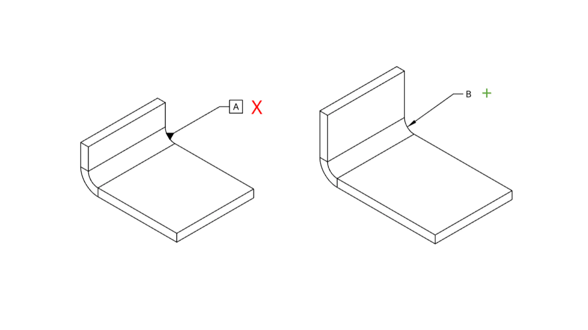
In air bending the blank spans the V-die and the punch pushes it down into the opening. If the flange is shorter than roughly half the die opening plus a landing, one side of the material hangs in open air instead of resting on the die shoulder. The punch then cams the part sideways: the angle varies along the bend, the flange curls, and the part twists.

SpecMin. flange length ≥ 4 × material thickness · practical minimum 3/16″ (4.8 mm)
// How to fix it
  1. Lengthen the flange to at least 4× material thickness measured from the outside of the bend.
  2. Our practical floor is 3/16″ (4.8 mm) on thin gauge, scaling up with thickness.
  3. If a short flange is unavoidable, ask about a hem — folding the material back on itself achieves a short, stiff edge.
  4. A narrower V-die may allow a shorter flange, but it also increases tonnage and tightens the achievable radius. Contact engineering before designing around it.
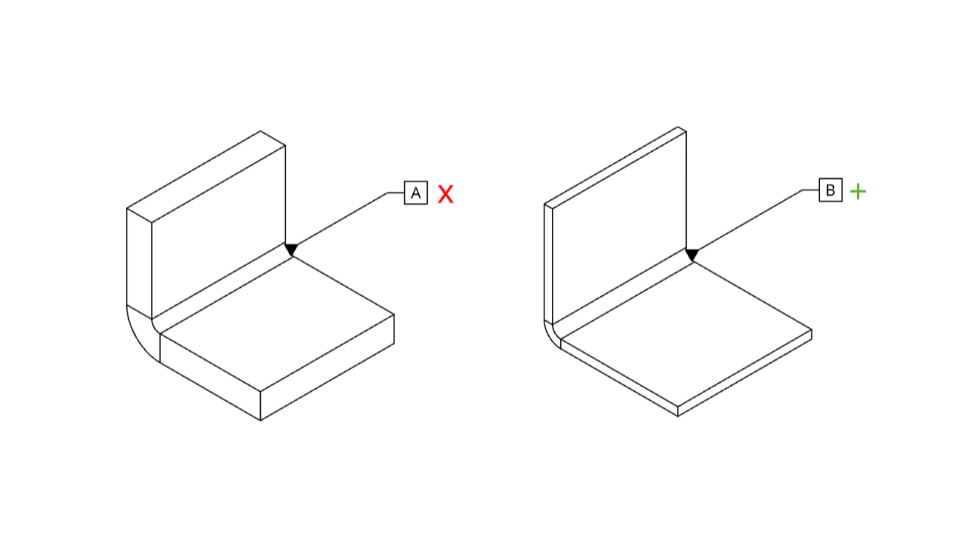
L-bracket comparison of a too-short flange versus a flange long enough to seat in the V-die
A flange shorter than the die opening cannot seat — the bend cams and twists along its length.
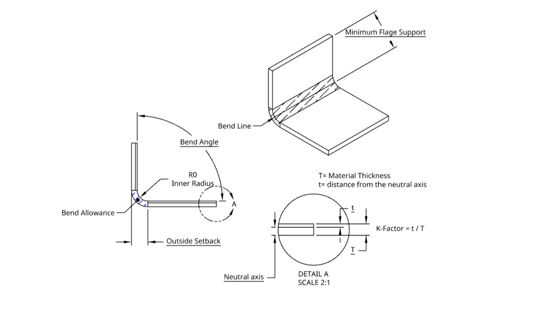
CAD diagram labelling bend angle, inner radius, bend allowance, neutral axis, K-factor and minimum flange support
The reference drawing for every bend term — including the flange support zone that must stay free of holes.
Video walkthrough Coming soon

What the quote app saysA single bending length is [xx] mm, with this thickness it may be a maximum of [xx] mm. · This bend exceeds the maximum bend length.

// What it means

One bend line is longer than the press brake can form in that thickness.

// Why it happens

Two limits stack up here. The brake has a physical bed length, and it has a tonnage rating: force needed rises directly with bend length, so a long bend in thick material can exceed the machine even though it fits the bed.

// How to fix it
  1. Shorten the bend, or split the panel into sections joined after forming.
  2. Drop to a thinner gauge — required tonnage falls roughly with the square of thickness.
  3. Use a larger V-die: a wider opening cuts tonnage substantially, at the cost of a larger inside radius.
  4. Check the tonnage yourself before redesigning.
ACB laser angle measurement system on the press brake
ACB measures each bend in real time and corrects for springback across the run.
Video walkthrough Coming soon

What the quote app saysThe bending angle is %detectedValue% degrees, with this thickness it may be a minimum of %minimumValue% degrees.

// What it means

You have specified an acute bend the tooling cannot reach in that gauge.

// Why it happens

To bend past 90° the punch must penetrate deep into the V-die. The included angle of the punch and die set the floor: an 88° punch cannot make a 30° bend. Thicker material takes up more of the die opening, so the achievable minimum angle opens up as gauge increases.

// How to fix it
  1. Open the bend angle out toward 90°.
  2. For very acute bends, ask about acute tooling or a two-stage bend-then-close operation.
  3. Confirm you modelled the included angle, not the complementary bend angle — this message is often a drawing convention mix-up.
ACB laser angle measurement system on the press brake
ACB measures each bend in real time and corrects for springback across the run.
Video walkthrough Coming soon

What the quote app saysProduct exceeds maximum bending angle

// What it means

The bend rotates the flange further than the tooling can carry it in one hit.

// Why it happens

Every punch and die combination has a working range. Past its limit the material has to be over-bent beyond where the tooling can reach, or the flange collides with the punch body on the way round.

// How to fix it
  1. Split a very tight fold into two bends with a short flat between them.
  2. Increase the inside radius so the same wrap needs less punch penetration.
  3. Ask about hemming if the intent is to fold the material fully back on itself.
Diagram coming soon
Video walkthrough Coming soon
// Related Press brake tooling library →

What the quote app saysBending exceeds maximum bending radius · Product exceeds maximum bending radius.

// What it means

The inside radius you modelled is larger than any V-die in our set can produce as a single bend.

// Why it happens

In air bending the inside radius comes from the die opening — roughly 16% of the V width for mild steel. A very large radius needs a very wide die, and past a point it is no longer a bend at all but a rolling operation.

SpecAir bend inside radius ≈ 0.16 × V-die opening (mild steel).
// How to fix it
  1. Reduce the inside radius. For most designs a radius equal to material thickness (1T) is ideal and costs nothing extra.
  2. If a large radius is functional, produce it as a series of small stepped bends (bump forming) — tell us and we will program it.
  3. True large-radius curves need rolling, which is a separate operation from press brake work.
Cracked outer surface on a too-tight bend radius next to a correctly radiused bend
Below 1T the outer fibre exceeds its elongation limit and cracks. At or above 1T material flows cleanly.
Video walkthrough Coming soon

What the quote app saysThe indicated bending radius is too small. An alternate radius will be applied.

// What it means

The inside radius in your model is tighter than our tooling produces in that material. The nearest achievable radius is substituted, which slightly changes flange dimensions.

// Why it happens

The inside radius is set by the die opening, not by the CAD model. Modelling a 0.010″ radius on 0.125″ plate does not make it producible — and a radius below 1T stretches the outer fibre past its elongation limit, cracking the bend. Hard alloys are worse: 6061-T6 needs 3T, 7075-T6 needs 4T.

SpecMin. inside radius: 1T mild steel & 5052 · 3T for 6061-T6 · 4T for 7075-T6
// How to fix it
  1. Model the inside radius equal to material thickness (1T) as your default.
  2. For 6061-T6 use 3T minimum; for 7075-T6 use 4T; 5052-H32 and mild steel are fine at 1T.
  3. Recalculate your flat pattern after changing the radius — bend allowance moves with it, so overall dimensions shift.
  4. Sheet Metal Gauge Chart
  5. Tap Drill Size Chart
  6. Countersink Size Chart
  7. Hardware Size Chart
  8. Min / Max Part Sizes
  9. Deburring Size Limits
  10. Slot & Tab Size Chart
  11. Bend across the grain wherever possible; bending along the rolling direction cracks far sooner.
Cracked outer surface on a too-tight bend radius next to a correctly radiused bend
Below 1T the outer fibre exceeds its elongation limit and cracks. At or above 1T material flows cleanly.
Video walkthrough Coming soon

What the quote app saysThickness is not equal to inner radius or half the outer radius. · Non-matching bend faces detected. The outer bend’s radius should be equal to the inner bend’s radius plus thickness.

// What it means

The geometry of the bend is internally inconsistent: the outer radius should always equal the inner radius plus the material thickness, and it does not.

// Why it happens

A real bend has concentric inner and outer surfaces separated by exactly the sheet thickness. When they disagree, the model was not built with a sheet metal bend feature — it was drawn with two independent fillets, or edited after the fact. The engine cannot derive a reliable bend allowance from it.

SpecOuter radius = inner radius + material thickness
// How to fix it
  1. Rebuild the bend using your CAD system's sheet metal tools so the outer face is generated from the inner radius plus thickness.
  2. Do not fillet the inside and outside edges separately to fake a bend.
  3. Verify: outer radius = inner radius + thickness, on every bend.
CAD diagram labelling bend angle, inner radius, bend allowance, neutral axis, K-factor and minimum flange support
The reference drawing for every bend term — including the flange support zone that must stay free of holes.
Video walkthrough Coming soon
// Related Modelling perfect sheet metal →

What the quote app saysInsufficient distance between bending lines.

// What it means

Two bends sit so close together that the flat between them cannot be supported during the second bend.

// Why it happens

When the second bend is formed, the flat between the two bend lines has to lie across the V-die. If that flat is narrower than the die opening, it drops into the vee instead of spanning it — the part rocks, the angle wanders, and the first bend gets crushed by the punch.

SpecFlat between bends ≥ 4 × thickness (more for wide dies)
// How to fix it
  1. Increase the flat between bends to at least 4× material thickness, plus the die opening where possible.
  2. Combine two shallow bends into one larger radius if the profile allows.
  3. For a tight offset (a Z-bend or joggle), tell us — dedicated offset tooling forms both steps in one hit.
CAD diagram labelling bend angle, inner radius, bend allowance, neutral axis, K-factor and minimum flange support
The reference drawing for every bend term — including the flange support zone that must stay free of holes.
Video walkthrough Coming soon

What the quote app saysMaximum [xx] bends allowed per product.

// What it means

The part has more bends than the instant quote engine will price automatically.

// Why it happens

Every bend is a separate setup step and a separate handling. Past a certain count the sequencing, tool changes, and collision checks stop being predictable enough to price without an engineer looking at it.

// How to fix it
  1. Reduce the bend count — often two bends can become one larger radius, or a stiffening flange can be dropped.
  2. Split the part into two simpler pieces joined by hardware.
  3. Send the file to quote@xeonnc.com for a manual quote — a high bend count is not a refusal, just not an instant price.
Diagram coming soon
Video walkthrough Coming soon
// Related Press brake capabilities →

What the quote app saysNon-concentric bending detected.

// What it means

The inner and outer surfaces of a bend are not concentric — they do not share a common center.

// Why it happens

A press brake bend wraps material around a single punch nose, so both surfaces are arcs about the same center. Non-concentric faces come from stretched or manually edited geometry, or from a "bend" that is really a lofted or swept surface.

// How to fix it
  1. Rebuild the bend with a sheet metal flange feature.
  2. Remove any scaling or non-uniform stretch applied to the model after the bend was created.
  3. Confirm that both bend faces are cylindrical, not conical or lofted.
Diagram coming soon
Video walkthrough Coming soon
// Related Modelling perfect sheet metal →

What the quote app saysIt is not possible to bend this product. The ratio between the width and height is not allowed.

// What it means

The proportions of the part make the bend physically unreachable — typically a very deep, very narrow channel or box.

// Why it happens

The punch has to descend between the existing flanges to reach the bend line. In a deep narrow section the punch body fouls the standing walls before the ram reaches the bottom of its stroke. Gooseneck tooling buys clearance, but it too has a limit.

// How to fix it
  1. Widen the channel, or reduce the flange height.
  2. Split into two L-shaped pieces joined back to back.
  3. Ask about gooseneck or offset tooling — it may clear a case that standard punches cannot.
Diagram coming soon
Video walkthrough Coming soon

What the quote app saysA complex bend combination has been detected. Manual verification is required.

// What it means

The bend pattern is producible in principle, but the sequence needs a human to confirm before the job runs.

// Why it happens

Automatic sequencing works by simulating each bend against the tooling and backgauge. When several bends interact — opposing flanges, tabs that fold over each other, closed corners — the solver finds a candidate order but cannot guarantee it, so an engineer checks it.

// How to fix it
  1. No change needed. The quote proceeds; our team verifies the bend sequence before production.
  2. If you want to remove the flag, simplify the interacting bends or increase the clearance between folded features.
  3. Expect a call if the sequence turns out to need a design tweak.
ACB laser angle measurement system on the press brake
ACB measures each bend in real time and corrects for springback across the run.
Video walkthrough Coming soon
// Related Part-on-part collision guide →

What the quote app saysThe folded sheet metal terminates with a bend feature having no successive flange.

// What it means

A bend runs right to the edge of the material — there is no flat left after the radius.

// Why it happens

The brake needs material past the bend to hold and to define the angle. A bend that terminates in the middle of its own radius has nothing for the tooling to control, so the angle is unrepeatable.

// How to fix it
  1. Extend the material past the bend by at least the minimum flange length (4T).
  2. If you wanted a rounded edge rather than a bend, model it as an edge break and specify deburring instead.
  3. Check the model for a flange that was trimmed back after the bend was created.
L-bracket comparison of a too-short flange versus a flange long enough to seat in the V-die
A flange shorter than the die opening cannot seat — the bend cams and twists along its length.
Video walkthrough Coming soon
// Related Minimum leg length calculator →

What the quote app saysConsecutive bends without a flange in between.

// What it means

Two bend radii run directly into each other with no flat section between.

// Why it happens

Back-to-back radii cannot be formed as two press brake hits — there is nothing to gauge against and nothing to support on the die. It is really a single curved section, and the brake makes straight bends.

// How to fix it
  1. Add a flat between the two bends, at least 4× thickness.
  2. Merge the two bends into one larger radius.
  3. If the profile is genuinely curved, it needs roll forming or bump forming — tell us the intent and we will program a stepped approximation.
Diagram coming soon
Video walkthrough Coming soon
// Related Bend layout calculator →

What the quote app saysBend reliefs are missing.

// What it means

Where two bends meet at a corner, there is no relief notch cut at the intersection.

// Why it happens

At an inside corner two bend zones try to stretch the same piece of material in different directions. Without a relief the metal tears at the corner, or bunches and lifts — leaving a raised, cracked corner that will not sit flat against a mating surface.

SpecRelief width ≥ 1T · depth ≥ radius + T · corner radius ≥ 1T
// How to fix it
  1. Add a relief notch at every corner where two bend lines meet.
  2. Make the relief at least as wide as the material thickness, and at least as deep as the bend radius plus thickness.
  3. Round the bottom of the relief — a radius equal to material thickness (1T) — never leave a sharp corner there.
  4. Most CAD sheet metal tools will add reliefs automatically if you enable auto-relief.
Sharp zero-radius interior corner compared with a corner carrying a deliberate relief radius
A zero-radius interior corner is a stress riser the laser physically cannot hit. Specify the radius.
Video walkthrough Coming soon
// Related Sheet metal design guide →

What the quote app saysThe distance from the hole to the bendline may lead to distortion. · Cutout too close to bending

// What it means

A hole or cutout sits inside the zone where material stretches during bending. It will come out oval, mispositioned, and out of size.

// Why it happens

In the bend zone the outer fibre stretches and the inner fibre compresses. Material flows toward whatever is weakest — and a hole is a hole. Instead of the strain distributing evenly, the metal pulls into the opening: the hole elongates along the bend, moves from its nominal position, and the flange around it distorts. A fastener will not seat.

SpecMin. hole-edge to bend line = inside radius + (2 × thickness) · use 3 × thickness for SS and 6061
// How to fix it
  1. Move the hole so the distance from its edge to the bend line is at least the inside radius plus 2× material thickness.
  2. Increase that to 3× thickness for stainless and 6061 — harder alloys distort more.
  3. If the hole cannot move, we can drill or punch it after bending. This adds an operation and cost, but the hole comes out true.
  4. Alternatively, extend the hole into a relief slot that crosses the bend line entirely, so there is no thin web to distort.
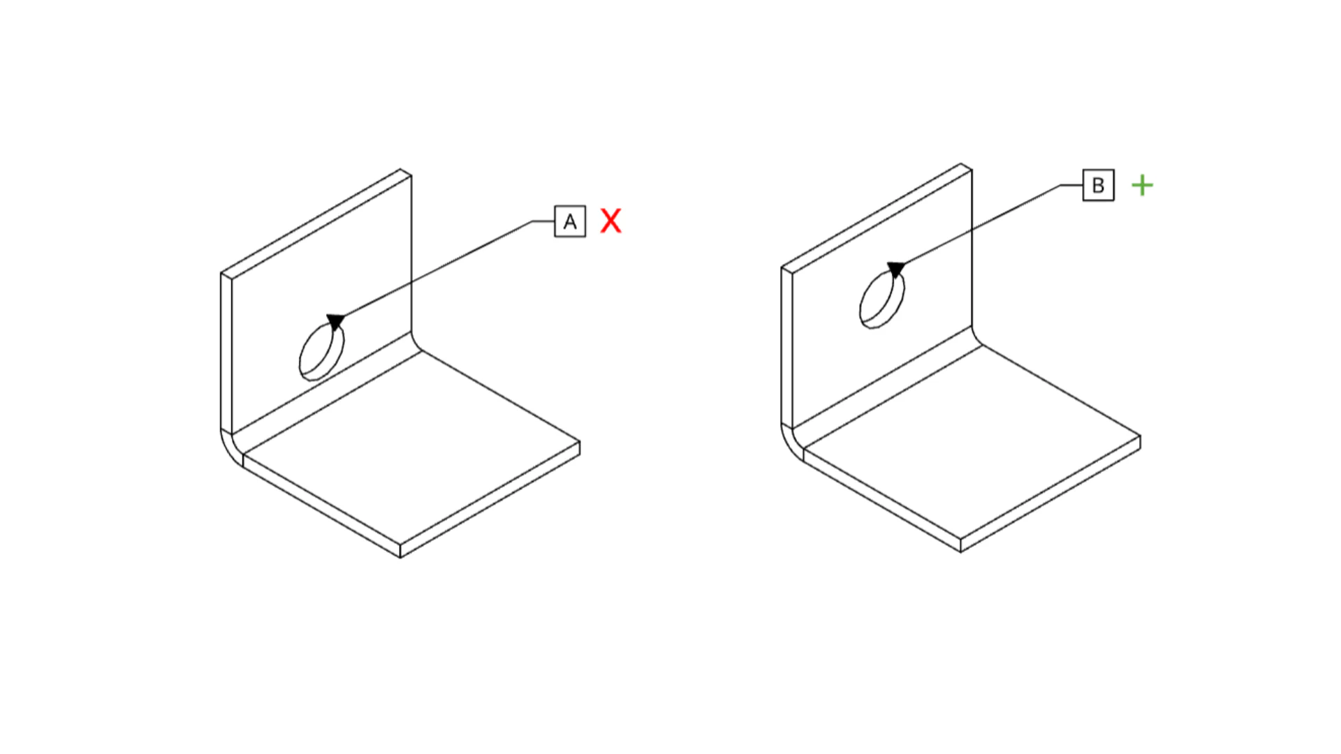
Incorrect and correct hole placement relative to a bend line, showing an ovalized hole
Left: hole inside the bend zone ovalizes. Right: same hole moved clear of the bend deformation zone.
CAD diagram labelling bend angle, inner radius, bend allowance, neutral axis, K-factor and minimum flange support
The reference drawing for every bend term — including the flange support zone that must stay free of holes.
Video walkthrough Coming soon
// 05 — Holes, Countersinks & Threads · 19 codes

Holes, Countersinks & Threads

Hole diameter versus process, countersink feasibility, tapping, and counterbores.

What the quote app saysHole diameter of %holeDiameter% is too small to cut, the system automatically configured it to be marked · Hole exceeds minimum diameter for cutting, its automatically configured to be marked

// What it means

The hole is below the minimum the laser can cut in this thickness and no drill is available for it, so it will be etched as a witness mark on the surface — not cut through.

// Why it happens

Two physical limits. First, kerf: if the hole is not comfortably wider than the beam, the cut path overlaps itself and the slug never drops. Second, heat: on a tiny circle the head slows right down, dwelling in one spot, which burns the hole oversize, hardens the edge, and warps the surrounding material. The safe floor is a hole diameter equal to material thickness — 1:1.

SpecMin. laser hole Ø = 1 × thickness (1.5 × for cleanest edge) · below 0.030″ expect marking
// How to fix it
  1. Enlarge the hole to at least 1× material thickness; 1.5× gives a genuinely clean edge.
  2. If the small hole is essential, request post-process drilling — we can drill below the laser minimum.
  3. Leave it marked deliberately if it is only a pilot location for the customer to drill later.
  4. For a whole pattern of tiny holes, scale the design up or switch to a thinner gauge.
Cross-section of a laser-cut hole showing minimum diameter D and the material wall each side
Minimum laser-cut hole diameter tracks material thickness — 1:1 as a floor, 1.5:1 for clean edges.
Video walkthrough Coming soon

What the quote app saysHole is too small to cut, the system automatically configured it to be drilled · Laser Cutting is not available for this hole. Therefore drilling is selected

// What it means

The hole is below the laser minimum, but a drill of that size is available. It will be drilled as a secondary operation — you get a true hole at the correct diameter.

// Why it happens

Drilling has no kerf and no heat-accumulation problem, so it reaches sizes the laser cannot. It is a separate setup, which is why it is called out.

// How to fix it
  1. No action needed — the hole will be produced correctly.
  2. Expect slightly longer lead time and a small cost for the drilling operation.
  3. If you want to avoid it, enlarge the hole to at least 1× material thickness so the laser can cut it.
Cross-section of a laser-cut hole showing minimum diameter D and the material wall each side
Minimum laser-cut hole diameter tracks material thickness — 1:1 as a floor, 1.5:1 for clean edges.
Video walkthrough Coming soon
// Related Minimum hole diameter rules →

What the quote app saysLaser cutting and drilling is not compatible with this hole. Therefore "marking" is selected for this hole. · This hole is not available for lasercutting and there is no available tool to drill. Automatically configured to be marked

// What it means

The hole is outside the laser range and there is no drill in the library that matches it, so only a surface mark will be produced.

// Why it happens

Drills come in discrete sizes. A hole that is too small to cut and does not match a stocked drill has no automatic route, so the engine falls back to marking rather than silently changing your diameter.

// How to fix it
  1. Round the diameter to a standard drill size — fractional, letter, number, or metric.
  2. Enlarge the hole to at least 1× material thickness so the laser can cut it.
  3. If the exact diameter matters (a bearing or dowel fit), specify a reamed hole and we will quote it as a machining operation.
Cross-section of a laser-cut hole showing minimum diameter D and the material wall each side
Minimum laser-cut hole diameter tracks material thickness — 1:1 as a floor, 1.5:1 for clean edges.
Video walkthrough Coming soon
// Related Hole & countersink guide →

What the quote app saysDetected countersink wont be processed for this hole, only the hole will be provided

// What it means

A countersink was detected in the model but cannot be produced on this feature. The through-hole will be cut; the conical seat will not.

// Why it happens

Countersinking needs a tool whose angle and diameter suit the hole, and enough thickness left under the cone to keep a land. When the combination does not exist in our tooling, the hole is produced plain rather than approximated.

// How to fix it
  1. Check the countersink angle: we run 82° imperial and 90° metric. Other angles have no tool.
  2. Verify the sheet is thick enough — a countersink that breaks through leaves a knife edge.
  3. Match the major diameter to our standard chart for the screw size you are using.
  4. If you need the screw flush, consider a flush-head self-clinching stud or a thicker gauge instead.
Diagram coming soon
Video walkthrough Coming soon

What the quote app saysThe angle of the countersink can not be produced

// What it means

The included angle of the cone in your model does not match any countersink tool we run.

// Why it happens

Countersinks are cut with a fixed-angle tool. The angle has to match the screw head or the head will not seat — it will rock on a line contact instead of bedding on the cone.

SpecAvailable: 82° imperial · 90° metric
// How to fix it
  1. Use 82° for imperial flat-head screws (the US standard).
  2. Use 90° for metric DIN/ISO flat-head screws.
  3. Check whether your CAD default wrote 100° or 118° — 118° is a drill point angle, not a countersink.
Diagram coming soon
Video walkthrough Coming soon
// Related Countersink angles explained →

What the quote app saysPart is too thin for countersink

// What it means

The cone would cut all the way through the sheet, leaving a knife edge instead of a seat.

// Why it happens

A countersink removes a cone of material whose depth is fixed by the screw size. If that depth is close to the sheet thickness, nothing is left underneath: the edge becomes razor thin, it deforms when the screw is tightened, and the head never seats square.

SpecMin. remaining land under the cone: 0.010″
// How to fix it
  1. Keep at least 0.010″ of flat land under the countersink.
  2. Move to a thicker gauge, or to a smaller screw size — cone depth scales with screw diameter.
  3. On thin sheet, use a flush-head self-clinching stud or a dimple/extruded hole instead of a countersink.
  4. A pan or button head screw with a plain hole is often the simplest answer.
Diagram coming soon
Video walkthrough Coming soon

What the quote app saysHole diameter is too wide for countersink

// What it means

The through-hole is nearly as large as the countersink major diameter, so there is almost no cone left to cut.

// Why it happens

A countersink is the difference between the major diameter at the surface and the minor hole below it. When the hole is oversized, that difference collapses and the feature stops being a seat.

// How to fix it
  1. Reduce the through-hole to the standard clearance diameter for your screw.
  2. Or increase the countersink major diameter to the standard value for that screw size.
  3. Check our countersink chart for matched major/minor pairs.
Diagram coming soon
Video walkthrough Coming soon
// Related Countersink dimension chart →

What the quote app saysThis Tapping type is not processable for this material type/thickness combination.

// What it means

The thread you specified cannot be tapped in that gauge and material.

// Why it happens

Thread strength comes from engagement length, which in sheet metal equals the sheet thickness. Thin material simply does not hold enough threads — a coarse thread in 0.060″ sheet gets about two turns of engagement and strips under any real torque. Hard and gummy materials add their own tapping limits.

// How to fix it
  1. Rule of thumb: sheet thickness should be at least the thread pitch × 2, and ideally ≥ 50% of the screw diameter.
  2. Use a self-clinching nut (PEM) instead — it gives full thread engagement in thin sheet and is stronger than a tapped hole.
  3. Move to a finer thread pitch, which gets more threads into the same thickness.
  4. Increase the gauge if the design allows.
Diagram coming soon
Video walkthrough Coming soon

What the quote app saysWe detected counterbore but we do not offer this service. The counterbores will not be processed.

// What it means

A flat-bottomed counterbore was found in the model. The through-hole will be produced; the counterbore will not.

// Why it happens

A counterbore is a flat-bottomed pocket — a milling operation, not a sheet metal one. It requires a machining setup that is not part of the laser-and-brake flow.

// How to fix it
  1. Use a countersink and a flat-head screw instead — that we do produce.
  2. Use a socket head screw with a plain clearance hole and accept the head standing proud.
  3. If the counterbore is essential, quote the part as CNC machining, or ask for a manual quote with a secondary machining operation.
Diagram coming soon
Video walkthrough Coming soon

What the quote app saysThe counterbore has been detected, but the required tool size is not available, so it cannot be executed.

// What it means

The counterbore diameter in your model does not match any tool in the library.

// Why it happens

Counterbores are cut at fixed tool diameters. A nominal size that falls between tools has no route.

// How to fix it
  1. Round the counterbore diameter to a standard size for the screw head you are using.
  2. Substitute a countersink and flat-head screw.
  3. Request a manual quote if the exact diameter is functional.
Diagram coming soon
Video walkthrough Coming soon
// Related Hole feature guide →

What the quote app saysThe depth of designed counterbore exceeds the limit.

// What it means

The counterbore is deeper than can be produced in that material thickness.

// Why it happens

The pocket has to leave sound material underneath. A counterbore approaching the sheet thickness leaves a thin membrane that tears out under the screw.

// How to fix it
  1. Reduce the counterbore depth so meaningful material remains below it.
  2. Move to a thicker gauge.
  3. Use a countersink, or a standoff / spacer to set the head height instead.
Diagram coming soon
Video walkthrough Coming soon
// Related Standoffs & spacers →
// 06 — Features & Engraving · 9 codes

Features & Engraving

Features cut into thickness faces, non-perpendicular edges, and engraving limits.

What the quote app saysThe body has features inside its thickness faces. · The body has features inside its thickness faces, which won’t be processed.

// What it means

There are details cut into the edge of the sheet — the narrow face that represents material thickness. They will not be produced.

// Why it happens

The laser cuts through the sheet from above. Anything modelled on the edge face — a chamfer, a slot in the edge, a partial notch — would have to be machined from the side, which is a different process entirely.

// How to fix it
  1. Remove chamfers and fillets from the thickness (edge) faces. Order deburring or edge rounding if you want the edge broken.
  2. Convert edge slots into full-depth cutouts in the face of the part.
  3. For a true machined edge feature, quote the part as CNC machining.
Diagram coming soon
Video walkthrough Coming soon
// Related Deburring & edge break →

What the quote app saysComplex unmatched features are detected inside the sheet faces.

// What it means

Features were found on one sheet face that have no counterpart on the other — pockets, embosses, or partial-depth details.

// Why it happens

A cut goes all the way through. Anything that exists on only one face is a forming or machining feature: a louver, an emboss, a dimple, a milled pocket. None of those come out of a laser and brake flow automatically.

// How to fix it
  1. Remove partial-depth features and replace them with through cutouts if the function allows.
  2. Louvers, embosses, and dimples need dedicated forming tooling — send the file for a manual quote.
  3. For milled pockets, quote as CNC machining.
Diagram coming soon
Video walkthrough Coming soon
// Related CNC machining →

What the quote app saysWarns that there are non-perpendicular cuts on edges. (non-orthogonal cutting angle)

// What it means

Some edges are cut at an angle through the thickness rather than square to the sheet.

// Why it happens

A flat-sheet fiber laser cuts vertically. Bevelled and drafted edges cannot be produced on the cutting table; they will come out square.

// How to fix it
  1. Remove the bevel from the model so the quote matches the produced part.
  2. If the bevel is a weld prep, tell us — it is a secondary operation.
  3. For a cosmetic edge break, order deburring instead of modelling a chamfer.
Diagram coming soon
Video walkthrough Coming soon
// Related Deburring & edge break →

What the quote app saysThe part has external engravings · Part contains engraving

// What it means

Surface engraving was found in the model and recognized as an engraving operation.

// Why it happens

Engraving is a low-power laser pass that marks the surface without cutting through. It is priced by marked length, separately from the cut path.

// How to fix it
  1. No action needed if the engraving is intended.
  2. If it was not — check for sketch geometry or an embossed logo left on the face — remove it to avoid the extra operation.
  3. Engraving is a surface mark: it will be removed or obscured by powder coating and heavy blasting.
Diagram coming soon
Video walkthrough Coming soon
// Related Laser capabilities →

What the quote app saysThe body contains inaccessible engravings.

// What it means

The engraving sits on a face the laser head cannot reach — usually an internal surface of a formed part, or a face that ends up on the inside after bending.

// Why it happens

Engraving happens on the flat blank before forming. Once the part is bent, the head has no access to the interior. If the engraved face is not exposed on the flat sheet, it cannot be marked.

// How to fix it
  1. Move the engraving to a face that lies flat and face-up on the blank.
  2. Remember the blank is engraved before bending — plan which side ends up outward.
  3. If the mark must be on an interior face after forming, tell us which face and we will confirm feasibility.
Diagram coming soon
Video walkthrough Coming soon
// Related All guides →

What the quote app saysIt is not possible to engrave products on both sides

// What it means

Engraving was found on both faces of the sheet. Only one side can be marked.

// Why it happens

The blank is cut and marked in a single pass with one side up. Marking the reverse means unloading, flipping, re-registering, and running again — the second side cannot be located accurately enough to be an automatic operation.

// How to fix it
  1. Consolidate all engraving onto one face.
  2. Decide which face is outward after forming and put the marking there.
  3. For genuine two-sided marking, request a manual quote — it can be done as a scheduled job.
Diagram coming soon
Video walkthrough Coming soon
// Related All guides →

What the quote app saysPlease note that engraving services are not available for this part. We will proceed with production and deliver the item without engraving.

// What it means

The part will be produced as ordered, but without the engraving.

// Why it happens

Engraving availability depends on material and finish. Some coated, plated, and film-covered materials cannot be marked cleanly, and on others the mark disappears under the finish.

// How to fix it
  1. Accept it if the mark was cosmetic.
  2. Ask about alternatives: a stamped label, an adhesive plate, or marking before finishing.
  3. Try a different material if the marking is a requirement.
Diagram coming soon
Video walkthrough Coming soon
// Related Finishing options →
// 07 — Tubes & Profiles · 8 codes

Tubes & Profiles

Tube and extruded profile geometry checks.

What the quote app saysProfiles and Tubes are not supported. · Profiles are not supported

// What it means

The uploaded body is an extruded profile or tube. Our instant quote covers flat sheet parts.

// Why it happens

Tube and profile work runs on a different machine with rotary axis handling, different nesting, and different pricing. It is not part of the flat-sheet flow.

// How to fix it
  1. If the part is genuinely sheet metal, check the model — a long narrow closed section can be read as a tube.
  2. For real tube and profile cutting, send the file to quote@xeonnc.com for a manual quote.
  3. Consider whether the section could be fabricated as a folded sheet metal channel instead.
Diagram coming soon
Video walkthrough Coming soon
// Related Shop capabilities →

What the quote app saysInforms that there are non-perpendicular cuts on edges (for tubes).

// What it means

The tube is cut at an angle rather than square across.

// Why it happens

Mitred and coped tube ends need a rotary or 3D cutting head. It is informational — the geometry is noted so it can be routed correctly.

// How to fix it
  1. No action needed if the angled cut is intended.
  2. Confirm the miter angle is dimensioned in your drawing.
  3. Send tube work to quote@xeonnc.com for a manual quote.
Diagram coming soon
Video walkthrough Coming soon
// Related All guides →

What the quote app saysAbnormal bend for a rectangular tube.

// What it means

A bend was found on a rectangular tube that does not match a standard tube bending geometry.

// Why it happens

Tube bending wraps the section around a die with a mandrel inside to stop it collapsing. Bends that are too tight for the section, or that fall too close to an end, do not match any standard setup.

// How to fix it
  1. Keep the bend radius at least 2–3× the tube width.
  2. Leave straight length at each end for the bender to grip.
  3. Send tube bending work for a manual quote.
Diagram coming soon
Video walkthrough Coming soon
// Related All guides →

What the quote app saysUncommon corner radius for a tube.

// What it means

The corner radii of the rectangular section do not match a standard mill-produced tube.

// Why it happens

Rectangular tube is formed and welded at the mill, and the corner radius comes out of that process — it is not a free parameter. A modelled radius that does not match any stocked section means no real material fits the model.

// How to fix it
  1. Look up the actual corner radius of the tube size you intend to use and model that.
  2. A common approximation is an outside corner radius of about 2× wall thickness.
  3. Confirm the section is one that is actually stocked before finalizing the design.
Diagram coming soon
Video walkthrough Coming soon
// Related All guides →

What the quote app saysInner and or Outer radiusses are incorrect designed. Inner radius must be the same as tube thickness and outerradius must be 2 times the tube thickness.

// What it means

The corner geometry of the tube does not follow the standard relationship to wall thickness.

// Why it happens

On mill-formed tube the inside corner radius equals the wall thickness and the outside equals twice the wall. Anything else describes a section that is not made.

SpecInner corner R = wall thickness · Outer corner R = 2 × wall thickness
// How to fix it
  1. Set inner corner radius = wall thickness.
  2. Set outer corner radius = 2 × wall thickness.
  3. Rebuild the section from the correct stock dimensions rather than sketching it by eye.
Diagram coming soon
Video walkthrough Coming soon
// Related All guides →

What the quote app saysThis tube's height and width do not match any available material. · This tube's diameter and thickness do not match any available material.

// What it means

The tube dimensions in your model do not correspond to a stocked size.

// Why it happens

Tube comes in fixed catalog sizes. A section drawn to arbitrary dimensions has no matching stock.

// How to fix it
  1. Pick a standard tube size and model to it exactly.
  2. Check both the outside dimensions and the wall thickness against the stock list.
  3. Ask us which sections we can source before committing the design.
Diagram coming soon
Video walkthrough Coming soon
// Related Material catalog →
// 08 — Finishing & Coating · 32 codes

Finishing & Coating

Size, weight, and hanging limits for coating, plating, blasting, grinding, and brushing lines.

What the quote app saysAssembly size is too big for powder coating · Assembly too heavy for Powder Coating · Part / Assembly too heavy for Sandblasting + Primer + Powder Coating · Part / Assembly too heavy for Primer + Powder Coating

// What it means

The part is larger or heavier than the coating line can carry. Which code you see tells you which package hit the limit: plain powder coat (3331 size, 3333 weight), sandblast + primer + powder (3346 / 3348 weight), or primer + powder (3351 / 3353 weight).

// Why it happens

Powder coating is a hanging line. Parts hang from hooks on a moving conveyor and pass through a cure oven, so both the oven opening and the hook rating are hard limits. Heavy parts also sag on the hook and mark where they contact it.

// How to fix it
  1. Split the part into sections that are coated separately and assembled after.
  2. Reduce gauge or add lightening cutouts to get under the weight limit.
  3. Ask about wet coating or an uncoated finish for oversized parts.
  4. Contact us with the part size — large-part coating can often be arranged as a scheduled job.
Parts hanging on a powder coating line
Coating lines hang parts on a moving conveyor — envelope and weight limits come from the hooks and oven.
Video walkthrough Coming soon

What the quote app saysAssembly needs to contain a cutout for powder coating · for Sandblasting + Primer + Powder coating · for Primer + Powder coating

// What it means

The part has no hole the coating line can hang it from.

// Why it happens

Every part on a coating line hangs from a hook, and the contact point stays bare — that is where the electrical ground is made and where the powder cannot reach. Without a hole there is nowhere to hang the part at all.

SpecHanging hole ≥ 1/4″ (6 mm) in a non-cosmetic location
// How to fix it
  1. Add a hanging hole, at least 1/4″ (6 mm), in an area where a small bare spot is acceptable.
  2. Put it on a hidden face — an inside flange, a mounting tab, a rear edge.
  3. An existing mounting hole can serve as the hang point; tell us which one to use.
  4. Expect a small witness mark at whichever point is used.
Parts hanging on a powder coating line
Coating lines hang parts on a moving conveyor — envelope and weight limits come from the hooks and oven.
Video walkthrough Coming soon
// Related Designing for powder coating →

What the quote app saysAssembly too big / too heavy for Hot Dip Galvanizing (3334 / 3335) · too big for Electro Galvanizing (3336) · too big / too heavy for KTL Coating (3337 / 3338) · too big / too heavy for Undercoating (3339 / 3340)

// What it means

The part is outside the tank envelope or the handling weight limit for the dip or electro-coating process you selected.

// Why it happens

These are all immersion processes: the part is lowered into a bath. Tank internal dimensions set the maximum size and the crane sets the maximum weight — neither can be stretched.

// How to fix it
  1. Split the part into sections that fit the tank.
  2. Choose a different finish: powder coating and wet coating have different envelopes.
  3. For hot dip galvanizing, remember the part also needs vent and drain holes so zinc can flow in and out — add them before quoting.
  4. Contact us for the current tank dimensions before redesigning.
Diagram coming soon
Video walkthrough Coming soon
// Related All finishing options →

What the quote app saysAssembly too big for Sandblasting · Assembly too heavy for Sandblasting

// What it means

The part exceeds the blast cabinet or blast room envelope, or the weight the fixture can hold.

// Why it happens

Blasting happens in an enclosed cabinet with media recovery. The part has to fit inside with room for the operator to reach every surface, and it has to be supported without collapsing the grate.

// How to fix it
  1. Split the part, or blast only the sub-assembly that needs it.
  2. Choose a chemical clean or a mechanical finish instead.
  3. Ask about hand finishing for oversized parts.
Diagram coming soon
Video walkthrough Coming soon
// Related Finishing options →

What the quote app saysAssembly too big for Wet Coating · Assembly too heavy for Wet Coating

// What it means

The part exceeds the spray booth envelope or the weight the racks can carry.

// Why it happens

Wet coating needs a ventilated booth and a drying area. Both are sized around the booth opening and the rack rating.

// How to fix it
  1. Split the part into coatable sections.
  2. Try powder coating instead — different line, different envelope.
  3. Contact us for booth dimensions before redesigning.
Diagram coming soon
Video walkthrough Coming soon
// Related Finishing options →

What the quote app saysAssembly too big for Pickling and Passivation · Assembly too heavy for Pickling and Passivation

// What it means

The part does not fit the acid tank, or exceeds the lifting limit for immersion.

// Why it happens

Pickling and passivation are immersion chemical processes for stainless steel. The tank dimensions and the hoist rating are hard limits, and the part must be fully submerged for the treatment to be uniform.

// How to fix it
  1. Split the part so each piece fits the tank.
  2. Ask about gel or paste passivation for large parts — applied by hand rather than by immersion.
  3. For welded stainless, mechanical cleaning of the heat tint is an alternative.
Diagram coming soon
Video walkthrough Coming soon

What the quote app saysAssembly is too big for grinding (3311) · too small for grinding (3312) · too heavy for grinding (3313)

// What it means

The part is larger, smaller, or heavier than the through-feed grinding machine can handle.

// Why it happens

Grinding runs on a wide-belt through-feed machine. Wide parts do not fit the band; short parts are not gripped by the feed rollers and get thrown; heavy parts overload the table.

// How to fix it
  1. For small parts, ask for hand finishing or run them as a tabbed gang sheet.
  2. For large parts, split the design or request hand grinding.
  3. Consider a different surface finish — brushing, blasting, or as-cut with deburring.
Diagram coming soon
Video walkthrough Coming soon
// Related Finishing options → Gang sheets →

What the quote app saysThe size of the part is not suitable for trowelizing

// What it means

The part falls outside the size range the deburring / edge-rounding (trowelizing) machine accepts.

// Why it happens

Like the other through-feed machines, the trowelizing line has a fixed working width and a minimum part footprint the rollers can grip.

// How to fix it
  1. Request hand deburring instead.
  2. Run small parts as a tabbed gang sheet so the sheet goes through the machine.
  3. Split oversized parts.
Diagram coming soon
Video walkthrough Coming soon
// Related Deburring guide →

What the quote app saysThe component is too large to be brushed (3401 / 3404) · too small to be brushed (3402 / 3405) · too heavy to be brushed (3403 / 3406)

// What it means

The part is outside the size or weight range of the brushing line. The paired codes cover the two brushing stations — the limit is the same in each case.

// Why it happens

Brushing is a through-feed abrasive process. The part must be wide enough to be gripped by the feed belt, narrow enough to fit the band, and light enough not to slip under the head. Parts outside that window either jam or come out with an inconsistent grain.

// How to fix it
  1. For small parts, request hand brushing, or have them cut as a tabbed gang sheet.
  2. For large parts, split the design or request hand finishing.
  3. Consider a different finish — a blasted or as-cut surface may suit the application.
  4. Remember brushing has a direction: tell us the grain direction you want relative to the part.
Diagram coming soon
Video walkthrough Coming soon
// Related Finishing options →
// 09 — Unsupported Services · 6 codes

Unsupported Services

Operations the instant quote engine does not price online.

What the quote app saysWelding is not supported. · Welding is not supported for the selected material. Please select another material.

// What it means

The upload includes welded joints or a welded assembly, which the instant quote engine does not price. On the second code, the material chosen is one we do not weld.

// Why it happens

Weld pricing depends on joint type, length, position, access, and required inspection — none of which can be read reliably from a CAD model. Some materials also need processes or shielding we do not run.

// How to fix it
  1. Upload the individual parts and order them cut and formed; weld them yourself or ask for a manual quote on assembly.
  2. Replace welded joints with self-clinching hardware, rivets, or tabs and slots — often cheaper and dimensionally more repeatable.
  3. For welded assemblies, send drawings and a weld callout to quote@xeonnc.com.
Diagram coming soon
Video walkthrough Coming soon
// Related Fastening without welding →

What the quote app saysThird party items are not supported.

// What it means

The assembly contains purchased components — fasteners, bearings, gas struts, electronics.

// Why it happens

The engine prices parts it manufactures. Catalog components have to be sourced and are not part of an automatic quote.

// How to fix it
  1. Delete purchased components from the assembly before exporting.
  2. Export only the parts you want manufactured.
  3. Self-clinching hardware is different — order it through the hardware insertion option rather than modelling the fastener.
Diagram coming soon
Video walkthrough Coming soon
// Related Hardware we install →

What the quote app saysMachining parts are not supported.

// What it means

The body is a machined part, not sheet metal, so it cannot be quoted through the sheet metal flow.

// Why it happens

Machined parts are priced from stock size, material removal, setups, and tolerances — a completely different model from cut-and-bend sheet work.

// How to fix it
  1. Quote the part through our CNC machining service instead.
  2. If it is meant to be sheet metal, rebuild it at constant thickness with bends rather than solid features.
  3. Parts that mix both — a sheet part with a machined feature — need a manual quote.
Diagram coming soon
Video walkthrough Coming soon

What the quote app saysNo fitting hardware found

// What it means

A hole was flagged for hardware insertion, but no self-clinching part in our catalog fits that hole diameter in that material and thickness.

// Why it happens

Self-clinching hardware is thickness-rated. Each nut, stud, and standoff has a minimum sheet thickness — around 0.040″ for the smallest sizes, up to about 0.093″ for larger threads — and needs an exactly sized mounting hole to clinch properly.

SpecSelf-clinching minimum sheet thickness: ≈0.040″ (small threads) to ≈0.093″ (all sizes)
// How to fix it
  1. Match the mounting hole to the hardware datasheet diameter exactly — clinch performance depends on it.
  2. Check the sheet is thick enough for the thread size you picked.
  3. Choose a smaller thread size, or move to a thicker gauge.
  4. Check the material: hardware must be harder than the sheet it clinches into, so very hard sheet limits the options.
Diagram coming soon
Video walkthrough Coming soon
// 10 — System Messages · 6 codes

System Messages

Generic engine faults with no specific design cause.

What the quote app saysUnknown error. · Unexpected error occurred. · Other calculation rule error. · Default · 4101

// What it means

The quote engine failed without identifying a specific design cause. This is a system-side fault, not something wrong with your design that we can name.

// Why it happens

These are catch-all codes returned when an internal step throws before a specific rule fires. The usual triggers are very large files, unusual geometry that breaks an assumption, or a transient service problem.

// How to fix it
  1. Try the upload again — a transient failure often clears on a second attempt.
  2. If it repeats, simplify the file: upload one part instead of an assembly, or re-export a fresh STEP.
  3. Send the file and the code you saw to quote@xeonnc.com. We can read the engine log and tell you exactly what failed.
Diagram coming soon
Video walkthrough Coming soon
// Related FAQ & support →

Fix it once, in CAD.

Every rule on this page exists because of something physical — a die opening, a beam width, a tank size. Design around them and your part goes from upload to production without a single engineering hold.