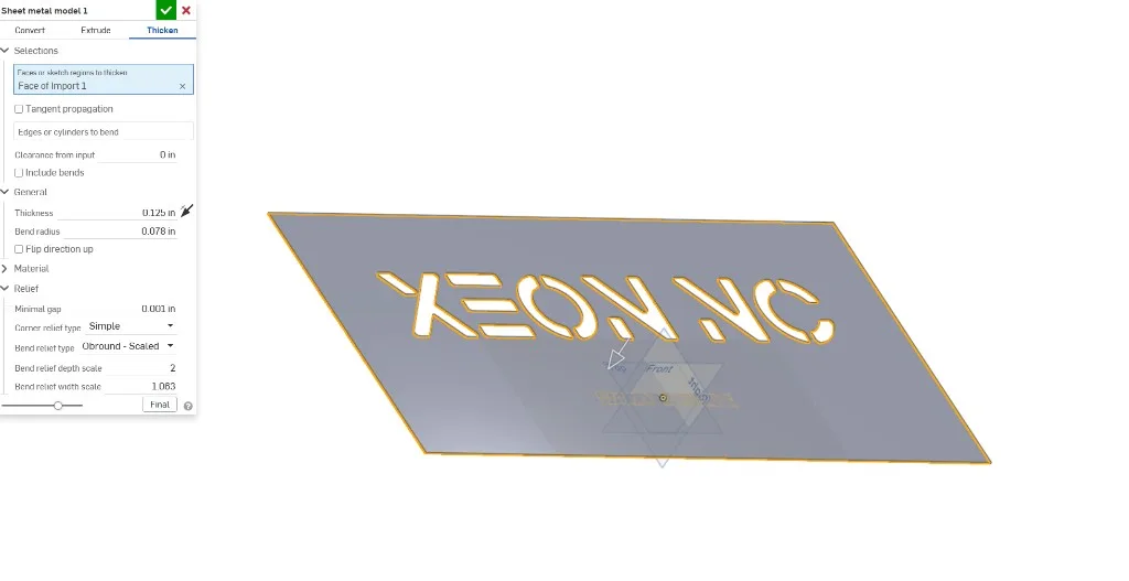
When two 90° flanges meet at a box corner, they can occupy the same space after forming. The published clearance is already on your material page — and you can calculate it here for any die we run.
Design Guide / Box Corners11 minute read
CORNER RELIEF / BEND LINE
The spec
MIN CORNER RELIEF
Formula
T − BD/2 + 0.015″
Find it under
LASER CUTTING
Worked 16 ga.
0.018″
90°
Two perpendicular flanges
A box corner, an enclosure wall, any pair of adjacent 90° legs folding toward each other.
BEND LINE
Measure on the flat
From each bend centerline to the edge of the other flange. Not on the folded model.
+0.015″
Forming clearance
Added on top of the geometric remainder so the edges miss after springback and coating.
NOT BEND RELIEF
A different problem
Bend relief stops tearing where a bend dies into remaining sheet. This spec stops two flanges from crashing.
Keep the flat-pattern distance from each bend line to the edge of the adjacent flange at or above Min Corner Relief Distance from Bend Line. If that clearance meets or exceeds the spec for your material, thickness, and die, the flanges form without colliding.
You can read the number on the material page Laser Cutting tab, or calculate it on this page by picking the alloy, the gauge, and the V-die. Both routes use the same formula: thickness minus half the 90° bend deduction, plus 0.015″ of forming clearance.
A box corner that looks closed in CAD is often two flanges occupying one space.
Constraint 01 / Geometry
T − BD/2
What the bend consumes
Half the 90° bend deduction is the material the radius pulls in from each flange. Subtract it from thickness and you have the remainder left at the corner before any pad.
Constraint 02 / Clearance
+ 0.015″
Room to form
Springback, coating build, and the fact that two cut edges are never perfectly square. Fifteen thousandths keeps the faces from kissing on the brake.
Design to this
MIN RELIEF
The published minimum
Listed per gauge on the Laser Cutting tab of every material page, and computed live below for any of the five TRUMPF V-dies we run.
Worked example — 0.060″ (16 Ga.) A1008 cold-rolled steel, W12 die.Thickness is 0.060″. The tabulated 90° bend deduction is 0.1147″. Corner relief = 0.060 − (0.1147 ÷ 2) + 0.015 = 0.018″. Put at least that much gap from each bend line to the adjacent flange edge and the corner forms clean.
02 / Why They Collide
Two walls, one corner, no leftover space.
A box, an enclosure, a pan with four sides: two adjacent flanges fold 90° toward each other and their vertical edges are supposed to meet. On the flat they already share a 90° internal corner. After forming, each flange has thickness, and that thickness has to live somewhere.
If the blank is cut so the two flanges meet at a sharp corner with no gap, the formed edges occupy the same volume. The brake stalls, the second flange walks, or the corner mushrooms. Building the clearance into the laser-cut blank is cheaper than discovering it on the press.
This is a formed collision, not a flat-pattern overlap. The blank can look perfectly legal unfolded and still crash when both walls come up. That is why the spec is measured from the bend lines on the flat — those lines tell you where the walls will stand after the hit.
Closed corners in the solid model are a common trap.Sheet-metal CAD will happily knit two flanges into a theoretically sharp inside corner. The laser cannot cut negative space, and the brake cannot form two thicknesses into one. The relief has to exist as a cut in the blank.
03 / Find It on the Material Page
Materials, then Laser Cutting.
Every Xeon NC material page publishes the number for the exact gauge you are ordering. You do not have to derive it unless you are changing dies.
01
Open Materials.
Start at the material catalog. Pick the alloy family you are actually ordering — 5052-H32, A1008 CR, 304, and so on. The spec is per gauge, not a universal rule of thumb.
02
Pick the thickness.
Use the gauge strip on the material page. A number that was comfortable on a 16 Ga. prototype is not the number for 1/8″ production stock, because the die — and therefore the bend deduction — changed with it.
03
Open the Laser Cutting tab.
The relief is a laser-cut gap in the blank, so it lives with the other cut rules. Click Laser Cutting next to Bending and Deburring & Finish.
04
Read Min Corner Relief Distance from Bend Line.
That row is the design minimum. Example: 0.063″ 5052-H32 — open Laser Cutting and use the published value, or confirm it in the calculator below.
Opens the 0.063″ 5052-H32 material page already on Laser Cutting. The highlighted row is Min Corner Relief Distance from Bend Line. Use the gauge strip for any other thickness, or start from the material catalog.
TWO DIFFERENT RELIEFSDO NOT SWAP THEM
CORNER
Min Corner Relief Distance from Bend Line — the gap that keeps two perpendicular flanges from occupying the same space after they fold up. This guide.
Use this
BEND
Bend Relief Depth / Width — a slot or notch where a bend terminates into remaining sheet so the metal does not tear. Different geometry, different failure.
On the flat pattern, the check is three steps. Do it in 2D even if the part was modeled in 3D — the laser cuts the unfolded blank, and that is where the collision is decided.
01
Extend each bend line past the flange edge.
Draw the bend centerlines through the corner as if they continued. You are creating the two datums the spec is written from.
02
Measure from each bend line to the edge of the other flange.
That distance is the corner relief. There are two of them at a box corner; both have to clear. Measure on the flat, not on the folded solid.
03
Compare to the spec for this gauge and die.
If the distance is equal to or greater than Min Corner Relief Distance from Bend Line, the flanges will not collide. If it is shorter, add a laser-cut notch or shorten a flange before you upload.
✗ Sharp corner / no relief
The two flanges share a 90° internal corner on the blank. After both 90° bends, their edges occupy the same space. The brake cannot finish the second wall.
✓ Relief from each bend line
The notch is measured from each bend centerline to the edge of the other flange. When that length is at least the published spec, the formed walls miss each other.
05 / Die Calculator
Pick the material. Then pick the die.
The production-assigned V-die is selected automatically for the gauge. Override it to see what a tighter or wider opening does to the corner gap. The formula does not change; the 90° bend deduction does.
Min Corner Relief Distance from Bend Line
Xeon NC TRUMPF air-bend data · T − (BD@90° ÷ 2) + 0.015″
The die marked production default is the tool assigned to this gauge. Switching dies recomputes bend deduction from that die’s inside radius and this SKU’s K-factor.
SPEC
Min corner relief
—
From each bend line
Thickness T
—
Nominal gauge
BD @ 90°
—
Bend deduction
Inside R / K
—
Used in the math
Formed corner / gap at the spec
This calculation
06 / The Formula
Thickness, half the deduction, plus fifteen thou.
The spec is not a guess. It is the remainder left at the corner after the 90° bend has consumed its share of the blank, plus a fixed pad so the cut edges miss in the real world.
Bend allowance at 90°
BA = (π/2)(IR + K × T)
Arc length of the neutral axis through a 90° bend. IR is set by the V-die. K comes from the material family we actually form.
Bend deduction at 90°
BD = 2(IR + T) − BA
What you subtract from the sum of the outside flange dimensions to get the flat. Tabulated on every material page for the assigned die.
Corner relief
T − (BD ÷ 2) + 0.015″
Half the deduction is the pull-in from one flange. Subtract it from thickness, then add 0.015″ of forming clearance. Floor at 0.010″.
16 Ga. A1008 CR, W12
0.018″
T = 0.060″, BD@90 = 0.1147″. 0.060 − 0.05735 + 0.015 = 0.01765, reported as 0.018″.
When you keep the production-assigned die, the calculator uses the tabulated 90° deduction from our TRUMPF tooling tables — the same number on the Bending tab of the material page. When you pick a different die, it recomputes deduction from that die’s inside radius (approximately 0.16 × V-opening) and the SKU’s K-factor, so you can see the effect of a tighter or wider V before you ask for a special setup.
Bend deduction lives on the Bending tab.If you want to run the arithmetic by hand, open the same material page, stay on Bending, and read the 90° cell in the bend-deduction strip. Plug it into the formula above. The Laser Cutting row is that result, already evaluated.
07 / 3D Preview Caveat
The preview is not a collision guarantee.
Our quoting system’s 3D view is a good visual reference for the folded part. It is not a press-brake simulation, and it cannot guarantee that two perpendicular flanges will miss at the corner.
The mesh is built from the developed blank and the assigned radius. It does not model springback over-bend, coating thickness, or the last few thousandths of flange walk as the punch bottoms. A corner that looks closed-but-fine in the preview can still crash on the brake.
Designing with the published clearance — or with the number from the calculator for the die that will actually run — is the only sure way. Use the preview to see the part. Use the spec to release it.
08 / CAD Tips
Set the shop numbers before you fold.
Most colliding corners are not modeling errors. They are K-factor errors: the solid was unfolded with a generic 0.44 and a 1T radius, then the shop formed it with a different deduction.
01
In 2D DXF, this check is mandatory.
A flat file has no folded state for software to inspect. Extend the bend lines and measure. If you are sending DXF, you are the collision detector.
02
In 3D, load our thickness, K-factor, and inside radius.
Pull them from the material page for the gauge you are ordering. The unfolded blank then matches the blank we will cut, and the corner gap you modeled is the gap that arrives at the brake.
03
The bend simulator unfolds. It does not flag this collision.
The Xeon NC bend simulator is the right place to see developed length, radius, and die-shoulder keep-out for holes. It does not currently highlight two adjacent flanges crashing at a box corner. Run the measurement on the flat, or use the calculator above.
04
Do not close the corner with a weld in CAD and call it formed.
If the design needs a sealed corner, that is a weld after forming, not a zero-gap pair of flanges. Model the relief, form the box, then weld. The laser still has to cut a gap.
05
In Onshape, this number is a floor — not every field in Sheet metal model.
Use it as the minimum for Square - Sized or Round - SizedCorner relief width, then confirm on the flat that each flange edge still sits at least that far from the other bend line. For a Simple or Closed corner with no sized notch, set Minimal gap to this value so Onshape does not model a 0.02 mm kiss. The next section walks through the exact dialog, using a 0.125″ Xeon NC plate as the example. Do not paste the number into Bend relief width or a 1.00–2.00 Corner relief scale — those are different constructions.
Onshape’s default Minimal gap is 0.02 mm (about 0.0008″).That is a CAD-kernel epsilon so two edges can rip, not a forming clearance. Our 16 Ga. spec is 0.018″ — more than twenty times larger. Leaving the Onshape default will look closed in the Part Studio and collide on the brake. A 1× thickness sized corner relief is always safer than the minimum and still laser-cuts cleanly; use the calculator number as the floor, not the aesthetic.
09 / Onshape Sheet Metal Model
Put the number in Minimal gap. Fix the radius too.
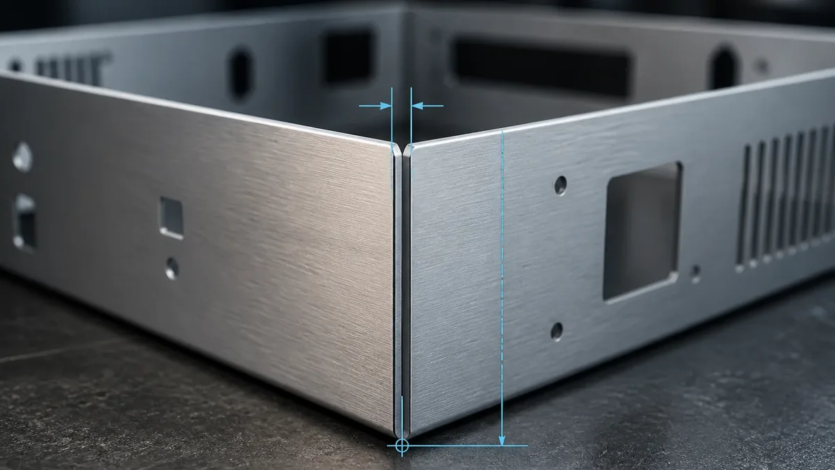
This is the Sheet metal model dialog on a 0.125″ plate thickened from an imported face. Thickness is right. Minimal gap and Bend radius are not.
Sheet metal model 1Relief section, still on Simple. Minimal gap is 0.001″ — a thousandth of an inch, which is CAD clearance, not forming clearance. When two 90° flanges meet, that is the field to raise to Min Corner Relief Distance from Bend Line.
Open the Relief group. With Corner relief type set to Simple, Onshape does not cut a square or round notch. The only air it leaves between two meeting walls is Minimal gap. Whatever you type there is the rip width in the flat and the seam gap in the folded model.
Sheet metal model field
This example (screenshot)
Use this for 0.125″ 5052-H32
Why
Thickness
0.125″
0.125″
Already correct. Match the gauge you will order.
Bend radius
0.078″
0.189″
0.078″ is a generic ~0.6T CAD default. We form this gauge in the W30 die. Inside radius is 0.189″ — from the material page, not from 1T.
K-factor (Material group)
Onshape default 0.45
0.44
Tabulated for 0.125″ 5052-H32. Wrong K puts the corner gap on the wrong place in the blank.
Minimal gap
0.001″
0.018″
T − (BD@90 ÷ 2) + 0.015″ with BD = 0.2447″. This is the floor for Simple corners. 0.001″ will collide.
Corner relief type
Simple
Simple, or Square - Sized ≥ 0.018″
Simple + the Minimal gap above is enough. A sized square is the safer visual notch if you want the relief obvious in the flat.
Bend relief type / scales
Obround, depth 2, width 1.063
Leave unless a bend dies into remaining sheet
That is tear-out relief, not flange-to-flange collision. Different problem, different guide.
Worked arithmetic for this plate, production W30 die: T = 0.125″, BD@90° = 0.2447″. Relief = 0.125 − 0.12235 + 0.015 = 0.018″. Confirm it in the die calculator by picking 0.125″ 5052-H32 and leaving the assigned V30 die selected.
01
Set thickness, then open Material and type our K-factor.
0.125″ stays. K-factor 0.44 for this 5052-H32 gauge. If you are on a different alloy, take K from the material page, not Onshape’s 0.45 default.
02
Replace the generic bend radius with our inside radius.
0.078″ will unfold a different blank than the W30 will form. Enter 0.189″ for 0.125″ 5052-H32. The calculator’s IR readout is the same number.
03
Set Minimal gap to the corner-relief spec.
For this plate that is 0.018″. If you later switch Corner relief type to Square - Sized, set Corner relief width to at least 0.018″ as well — do not leave Minimal gap at 0.001″ thinking the square will save it unless the square is actually that size.
04
Add flanges, then measure the flat.
This example starts as a flat stencil. The gap only matters once two perpendicular flanges exist. After you flange adjacent edges, open the flat view and measure from each bend line to the adjacent flange edge. It must still be ≥ 0.018″. Export the folded STEP as in the Onshape STEP export guide.
A 1× thickness sized relief is always legal.If you would rather not type 0.018″, set Corner relief type to Square - Sized and Corner relief width to 0.125″ on this gauge. That is larger than the floor, obvious on the blank, and still a clean laser cut. The 0.018″ number is the minimum that will form, not the notch you have to live with.
10 / If They Still Collide
Four honest options.
Sometimes the envelope, the hardware, or a mating lid fixes the corner and there is no room for the published gap. That is a real design problem with real solutions — none of which is hoping the brake will squeeze it through.
Shorten one flange
Cost: none
Drop one wall so its edge stops short of the other flange’s inside face by the spec. The corner is no longer theoretically closed, but it forms every time. This is the usual fix on covers and shallow pans.
Add a laser-cut corner notch
Cost: none
Keep both flange heights and cut a square or rounded relief at the intersection, sized to the published minimum from each bend line. The notch is what the Laser Cutting row is describing.
Offset one flange so the edges miss
Cost: none
Shift one bend line so the two vertical edges overlap into a lap instead of a butt. Useful when you want a weld prep or a fastener tab. The gap still has to exist; it just lives as a lap instead of a notch.
Form open, then weld the seam
Cost: one operation
Cut the relief, form the box, weld the corner closed. This is the production answer when the design needs a sealed interior and the flanges cannot be shortened. Call the weld out on the drawing so it is not treated as a forming defect.
Flag it rather than hide it.If a corner has to sit inside the guideline, note it when you upload. Alternate tooling, a different bend sequence, or a welded seam may solve it — but only if we know the closed corner is intentional.
11 / Release Checklist
Seven lines before you upload.
Each one takes seconds on the material page or in the calculator, and each one prevents a corner from stalling the brake.
Upload the formed STEP with the relief already in the blank.
Send the model with the material and thickness selected. We unfold against the die that will run the job. A corner that already clears the published spec forms the first time.
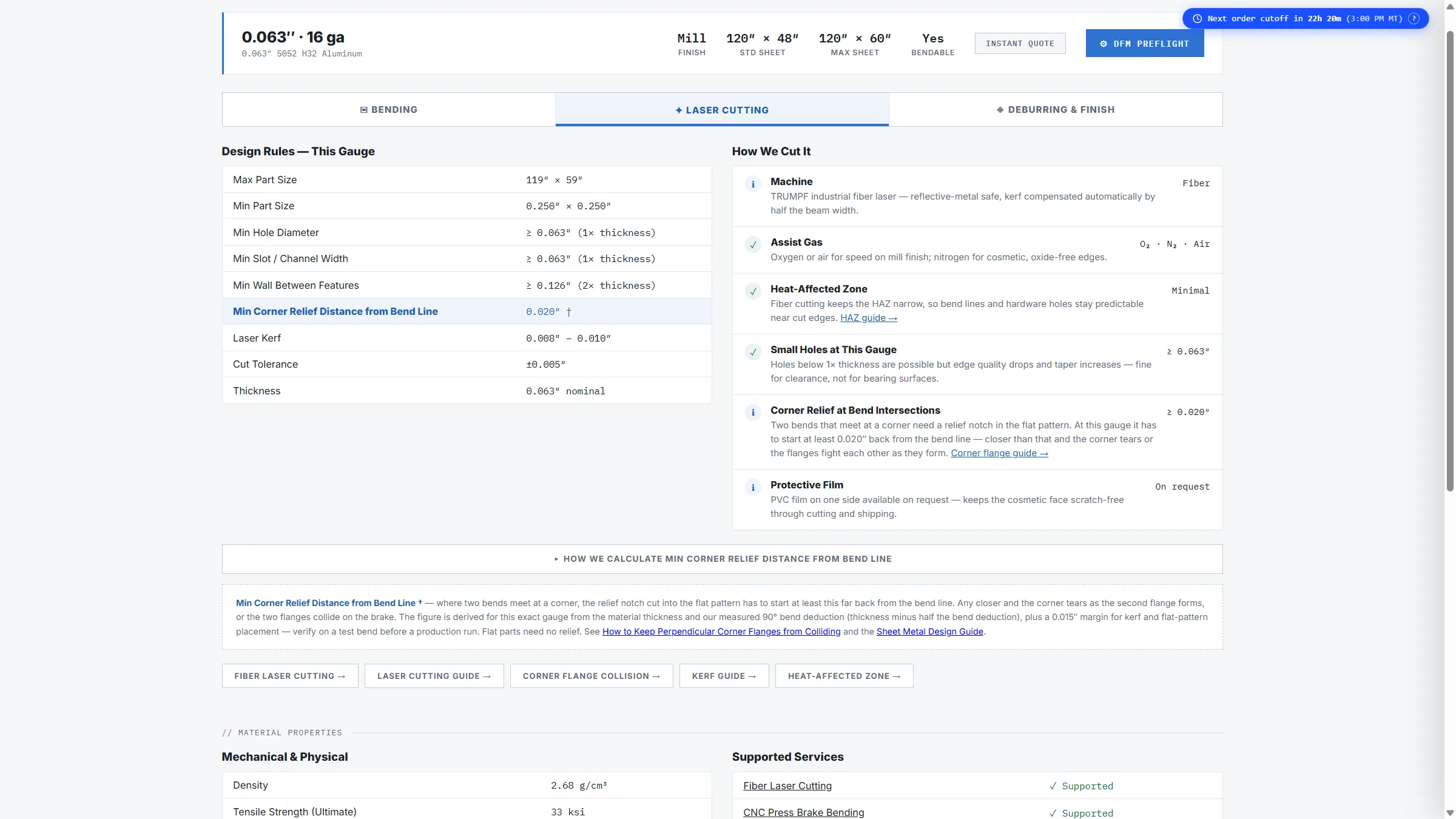 0.063″ 5052-H32 · Laser Cutting tabOpen this spec on the material page →