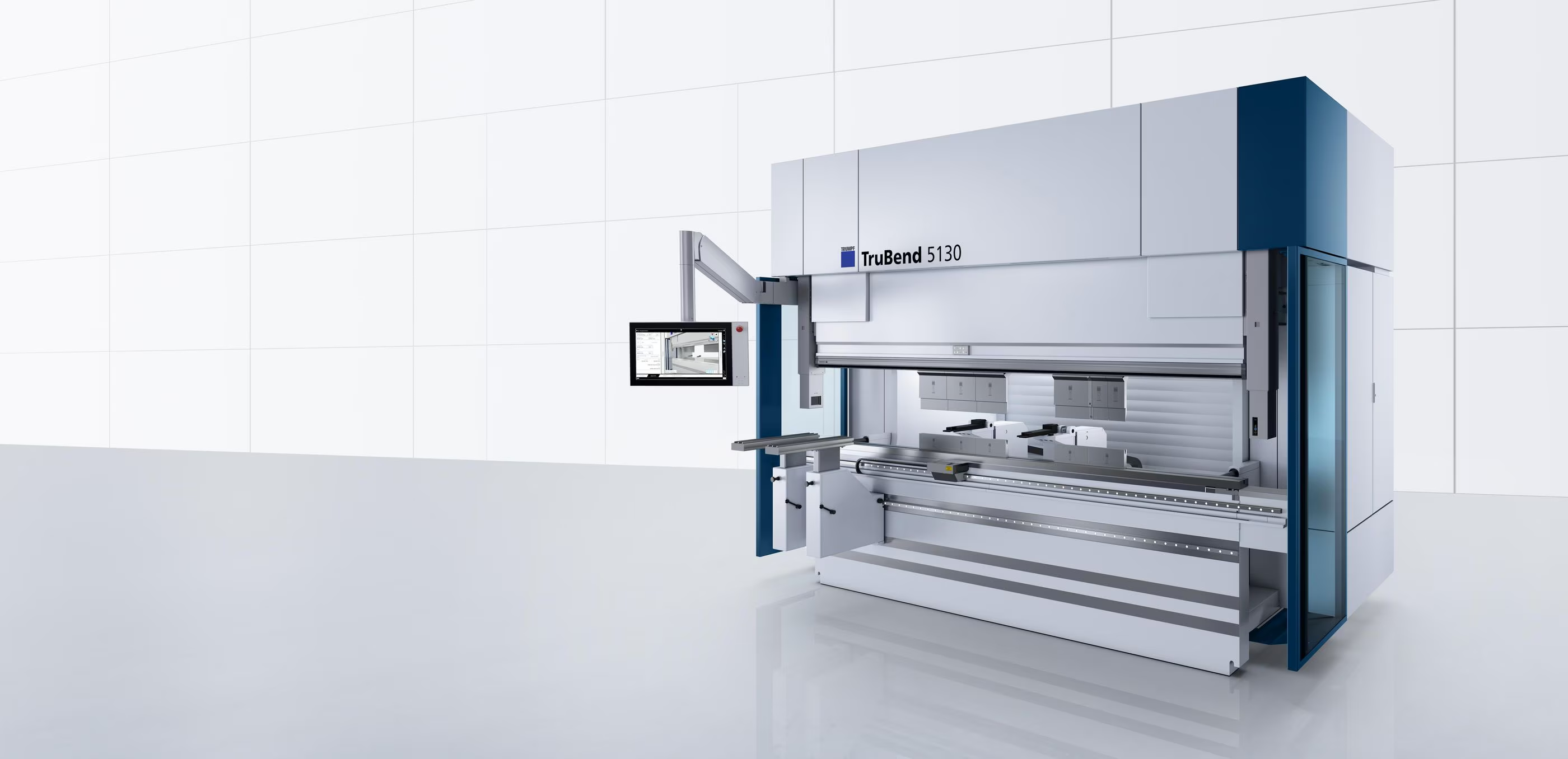
One number decides most of the part.
The inside bend radius looks like a small CAD field. It is actually the input that determines the developed flat length, the springback behavior, the safe distance to every nearby feature, and whether the outside of the bend cracks.
Designers reach for a bend radius the way they reach for a fillet: pick something that looks reasonable and move on. On a press brake that choice propagates. Change the inside radius and the neutral axis moves, which changes the bend allowance, which changes the blank. Change it again and the tangent lines move, which changes how far a hole has to sit from the bend. Change it far enough and the material on the outside of the bend runs out of elongation and splits.
None of that is exotic. It is just consequence. The useful framing is that the radius is not a preference—it is a specification with four dependents.
The bend allowance is an arc measured along the neutral axis. Its length is a direct function of the inside radius, the K-factor, and the angle. A different radius is a different blank.
A larger radius strains less of the section past yield, so more of the sheet springs back elastically. Radius and angle accuracy are the same problem.
Holes, slots, tapped features, and hardware are measured from the bend tangent. The tangent line moves outward as the radius grows.
Outside-surface elongation is approximately T ÷ (2Ri + T). Tighten the radius and that strain climbs quickly toward the material limit.
Air bending forms a natural radius.
The punch does not stamp its own tip shape into the sheet. It pushes the material into a gap, and the material chooses an arc.
In air bending—the method used for virtually all press-brake work at Xeon NC—the sheet touches the tooling at exactly three lines: the two die shoulders and the punch nose. It never reaches the bottom of the V. The bend angle is controlled by how far the punch descends, and the inside radius is whatever the material naturally forms while spanning the opening.
That natural radius is remarkably predictable. For the tooling and materials in our library it is close to 16 percent of the die opening, and it is essentially independent of the punch tip radius as long as the punch nose is sharper than the natural radius.
Two consequences fall out of this immediately. First, a designer cannot request an arbitrary inside radius and expect it for free—the request is really a request for a specific die. Second, the same die produces the same inside radius across every gauge it covers, which means the radius-to-thickness ratio is not constant.
Five radii cover the whole catalog.
Xeon NC forms sheet metal with a fixed set of WILA-style dies. That set produces exactly five standard inside radii, and material thickness decides which one you get.
This is the table to design against. If the radius in your model matches the value in the third column, your CAD flat pattern and our production flat pattern will agree, and the bend data behind the instant quote applies without adjustment.
| V-die | Opening | Inside radius | Thickness range | Min. formed flange | Typical use |
|---|---|---|---|---|---|
| W8 | 8 mm / 0.315″ | 0.050″ | 0.020″ – 0.048″ | 0.198″ | Light gauge: 24–18 Ga. steel and stainless, thin 5052 |
| W12 | 12 mm / 0.472″ | 0.076″ | 0.050″ – 0.075″ | 0.298″ | 16 and 14 Ga. steel, 0.050″–0.063″ aluminum |
| W20 | 20 mm / 0.787″ | 0.126″ | 0.080″ – 0.120″ | 0.496″ | 12 and 11 Ga. steel, 0.080″–0.100″ aluminum |
| W30 | 30 mm / 1.181″ | 0.189″ | 0.125″ – 0.188″ | 0.744″ | 10 Ga. through 3/16″ plate, 1/8″ aluminum |
| W50 | 50 mm / 1.969″ | 0.315″ | 0.250″ – 0.313″ | 1.240″ | 1/4″ and 5/16″ hot-rolled, stainless, 5052 |
Both derived numbers in that table come from the die opening. Inside radius is 0.16 × V and minimum formed flange is 0.63 × V, measured to the outside of the part. That is why the flange minimum grows in lockstep with the radius: a thicker part needs a wider die, a wider die needs more material on the shoulders, and both constraints tighten together.
The 1T rule breaks inside a die band
Because one die serves a range of gauges, the ratio of inside radius to thickness is highest at the thin end of each band and lowest at the thick end. The chart below plots real R/T for the gauges we form. Anything above roughly 2T is a case where a designer who modeled “1T” will get a noticeably different flat pattern than they expected.
Read that chart as a design signal rather than a warning. A 2.5T inside radius on 0.020″ aluminum is completely safe for the material—the risk is not cracking, it is a flat pattern that disagrees with the model by more than the tolerance on the part.
Check your gauge before you model.
Select the material family and thickness you plan to order. These are the values our bend data assigns to that combination.
The K-factor shown is the value our bend tables carry for that specific material and gauge—not a generic 0.44. It moves with alloy, temper, and die, which is exactly why a CAD default K-factor and a production flat pattern rarely land on the same blank.
Some alloys will not accept a tight radius.
Tooling sets the radius you receive. Material decides whether the radius you want is survivable at all.
The outside of a bend is in tension. Approximate outer-fiber elongation is T ÷ (2Ri + T), so a 1T radius stretches the outside surface by about 33 percent, a 2T radius by about 20 percent, and a 0.5T radius by about 50 percent. Compare those numbers against the alloy’s available elongation and the answer becomes obvious: soft, annealed, and H32-temper material has room; hard T6 tempers do not.
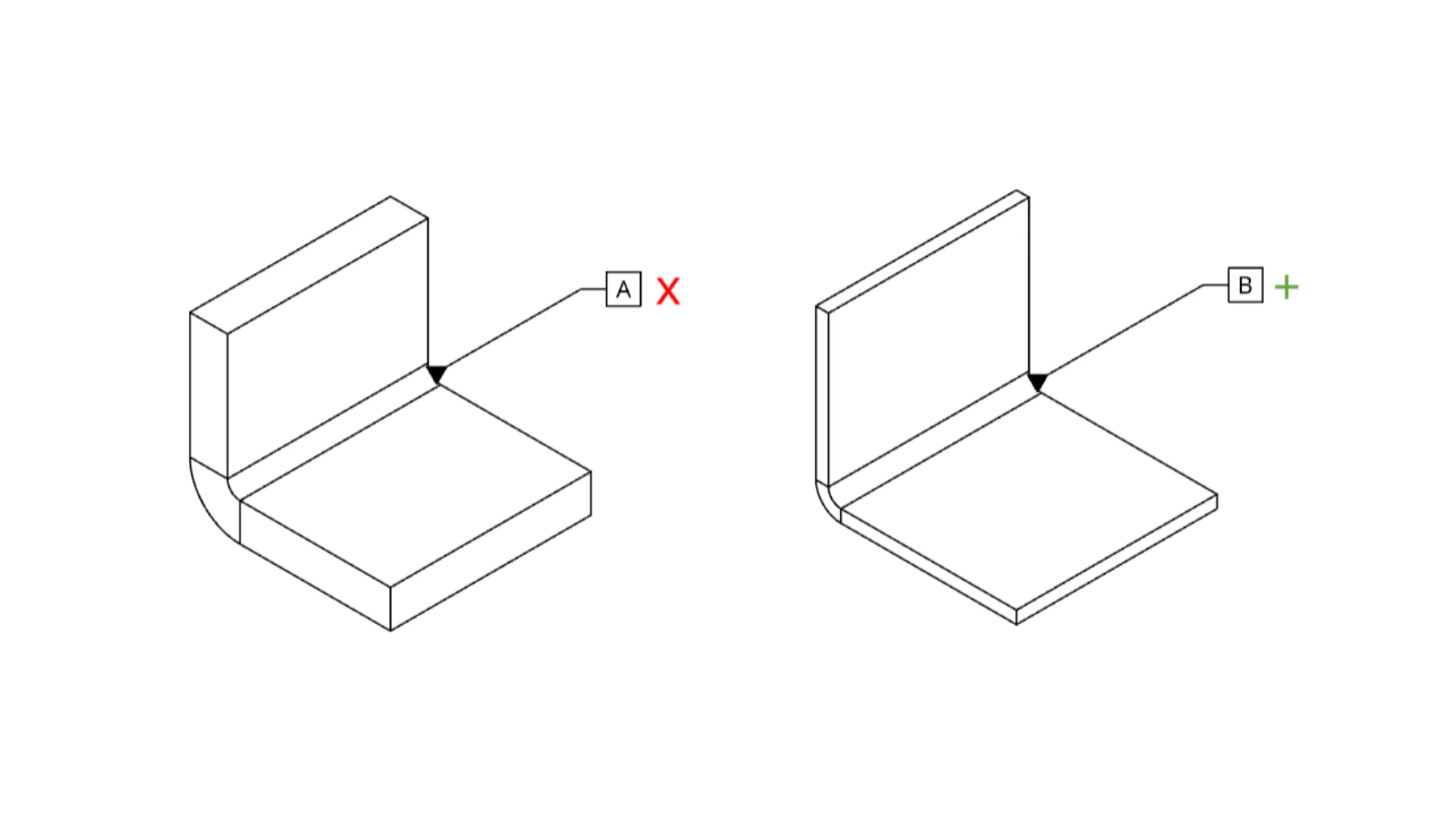
Typical minimum inside radius by material
The values below are conventional starting points for a 90° bend, expressed as a multiple of thickness. Treat them as screening guidance: exact minimums move with gauge, temper lot, and surface condition, and the quote preflight remains the authority.
| Material | Condition | Min. Ri across grain | Min. Ri with grain | Bend behavior |
|---|---|---|---|---|
| Aluminum 5052 | H32 | 0.5–1T | 1–1.5T | The sheet-metal workhorse. Forms cleanly at every standard radius we run. |
| Aluminum 6061 | T6 | 2.5–3T | 3.5–4T | Springs back hard and cracks readily. Most bend complaints on aluminum trace here. |
| Aluminum 7075 | T6 | 4–5T | 5T+ | Rarely cold formed. Usually machined or formed in the annealed condition and re-heat-treated. |
| Steel A1008 | Cold-rolled CS | 0.5–1T | 1–1.5T | Very forgiving. Consistent springback, excellent surface after forming. |
| Steel G90 | Galvanized | 0.5–1T | 1–1.5T | Base steel forms like CRS, but the zinc coating can flake or whiten at tight radii. |
| Steel A36 / A1011 | Hot-rolled P&O | 1–1.5T | 1.5–2T | More variation in thickness and yield, so more variation in formed angle. |
| Stainless 304 / 316 | Annealed, 2B | 0.5–1T | 1–1.5T | Ductile but work-hardens fast. Highest springback of the common sheet materials. |
| Steel A572 Gr 50 | HSLA | 1.5–2T | 2–2.5T | Higher yield means substantially more springback and more tonnage per foot. |
| Corten A588 / A606 | Weathering | 1.5–2T | 2–3T | Less forgiving than mild steel and prone to edge cracking from the cut edge. |
| AR500 | 500 BHN plate | 3–5T | 5T+ | Abrasion plate. Normally specified flat rather than formed. |
Grain direction is worth two columns
Rolled sheet has a grain. A bend line running perpendicular to the rolling direction stretches across the grain and tolerates a tighter radius. A bend line running parallel to it stretches along the grain and needs roughly 1.5 to 2 times the radius before the surface stays sound. On a single-bend part this costs nothing to control. On a four-sided enclosure, two of the bends will always be with the grain, which is why the with-grain column is the one to design against when the material is marginal.
Six rules that make the model match the part.
The goal is not to find the theoretically ideal radius. It is to model a radius that the brake will actually produce, so the flat pattern, the drawing, and the finished part all describe the same object.
What moves when the radius moves.
Changing the inside radius is never a local edit. Four other quantities change with it, and three of them can put a part out of tolerance without touching a single dimension on the drawing.
| Quantity | Direction of change | Practical consequence | How it is managed |
|---|---|---|---|
| Bend allowance | Grows with radius | The developed blank gets longer, so the finished flange lengths shift if the flat is held fixed. | Blank is developed from production bend data, not from a CAD default. |
| Springback | Grows with Ri/T | The part opens further after the ram retracts, and the effect varies with lot-to-lot yield. | Optical angle measurement corrects each bend in process. |
| Bend-affected zone | Grows with radius | Holes and slots that were clear become oval or pull toward the bend. | Clearance is re-checked against Ri + 2T from the tangent. |
| Minimum flange | Grows with die opening | A short leg that fit the previous die can no longer stay on the shoulders. | Flange minimum of 0.63 × V is validated at preflight. |
| Forming tonnage | Falls as the die widens | A wider die reduces force, which is why large radii are the cheap direction and tight radii are not. | Force scales roughly with T² ÷ V; long bends are checked against machine capacity. |
Springback deserves the extra sentence. It is not a fixed percentage that can be dialed in once. A 304 stainless part with a 1.5T radius recovers more than the same geometry in cold-rolled steel, and two coils of the same 304 spec can differ enough to matter on a ±0.5° part. That is the reason the brake measures the angle while the material is still under load rather than relying on a stored overbend value—see the ACB laser on our TRUMPF 5170.
Tighter, wider, and everything in between.
Standard air bending covers the large majority of parts. When a design genuinely needs something else, the process changes—and the change is worth knowing about before the drawing is released.
The pattern across all five is the same: leaving the air-bend envelope trades an automatic quote for an engineering conversation. That is often the right trade. It is rarely the right accident.
For the tooling reasoning behind die selection, see the tooling selection guide and the press-brake tooling library. For what happens to features near the bend, see the bend-affected zone guide.
Eight lines before you upload.
Every item below is something the preflight will check anyway. Checking them first is how a part quotes in one pass instead of three.
Upload the folded model and let the bend data do the rest.
Send the formed STEP with a realistic inside radius and the correct material and thickness. We will confirm the die, develop the blank, validate the deformation zones, and return a production-ready quote.
Upload your STEP →