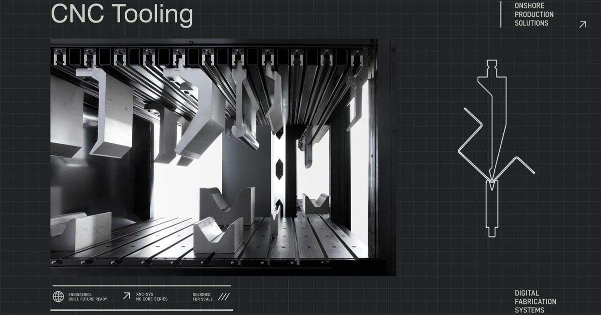
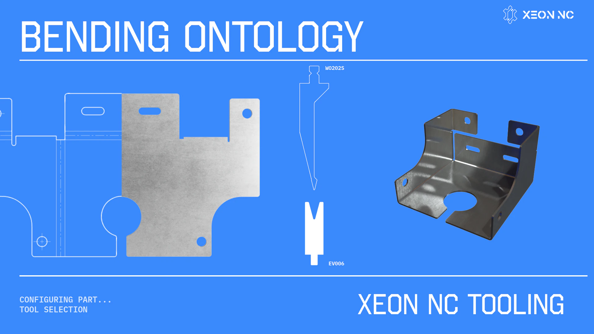
A press brake does not simply fold a line in a CAD model. It drives a punch, a sheet, and a die through a precisely managed physical event.
The punch defines where force enters. The V-die supports the sheet. The material yields, wraps around the punch tip, and springs back when the load leaves. Change the alloy, grain direction, thickness, inner radius, flange length, or angle and the event changes with it.
That is why bend quality begins before the machine moves. The geometry must be compatible with a real punch and die. Both flanges need support. The formed part needs room to rotate. The tooling must be able to leave after the bend. The sequence has to remain possible from the first stroke to the last.
The flat pattern is only the plan. The tooling is the truth.
FORMING SYSTEM / INPUTSSTATUS: PREFLIGHTED
PUNCH
Tip radius, included angle, profile, height, and clearance around earlier flanges.
SELECT
DIE
V-opening, shoulder radius, tonnage capacity, and minimum supported flange.
MATCH
MATERIAL
Alloy, temper, thickness, grain direction, tensile strength, and springback behavior.
VERIFY
GEOMETRY
Angles, radii, holes, reliefs, collisions, backgauge surfaces, and bend sequence.
SIMULATE
02 / The Shape Set
What we can bend.
From one-flange brackets to multi-bend chassis, the shape is not limited by what can be drawn. It is limited by whether the machine can support, reach, form, and release it.
PROFILE / L-01
OPEN / 1 PLANE
Single-flange profile
Standard
L-brackets and flanges
The most direct formed profile: one bend, two open legs, and clear access for straight tooling.
These are profile families, not standalone machine limits. The final decision still comes from material, thickness, bend length, tooling, flange support, and the complete bend sequence.
Shape pipelineA formed part is a chain of states: flat blank, assigned bend logic, selected tooling, verified sequence, finished geometry.
03 / Capability Is an Envelope
Any angle. Any flange. Inside a real operating envelope.
Our standard air-bending range is 30° to 135°, with a standard angle tolerance of ±0.5°. Bend lines can reach up to 120 inches when material, thickness, tonnage, and geometry permit.
Those numbers describe the machine's range, not a guarantee that every possible combination can be formed. A 120-inch bend in thin aluminum and the same bend in thick steel are different load cases. A 30-degree acute bend with a long open flange and the same angle inside a closed box create different access conditions.
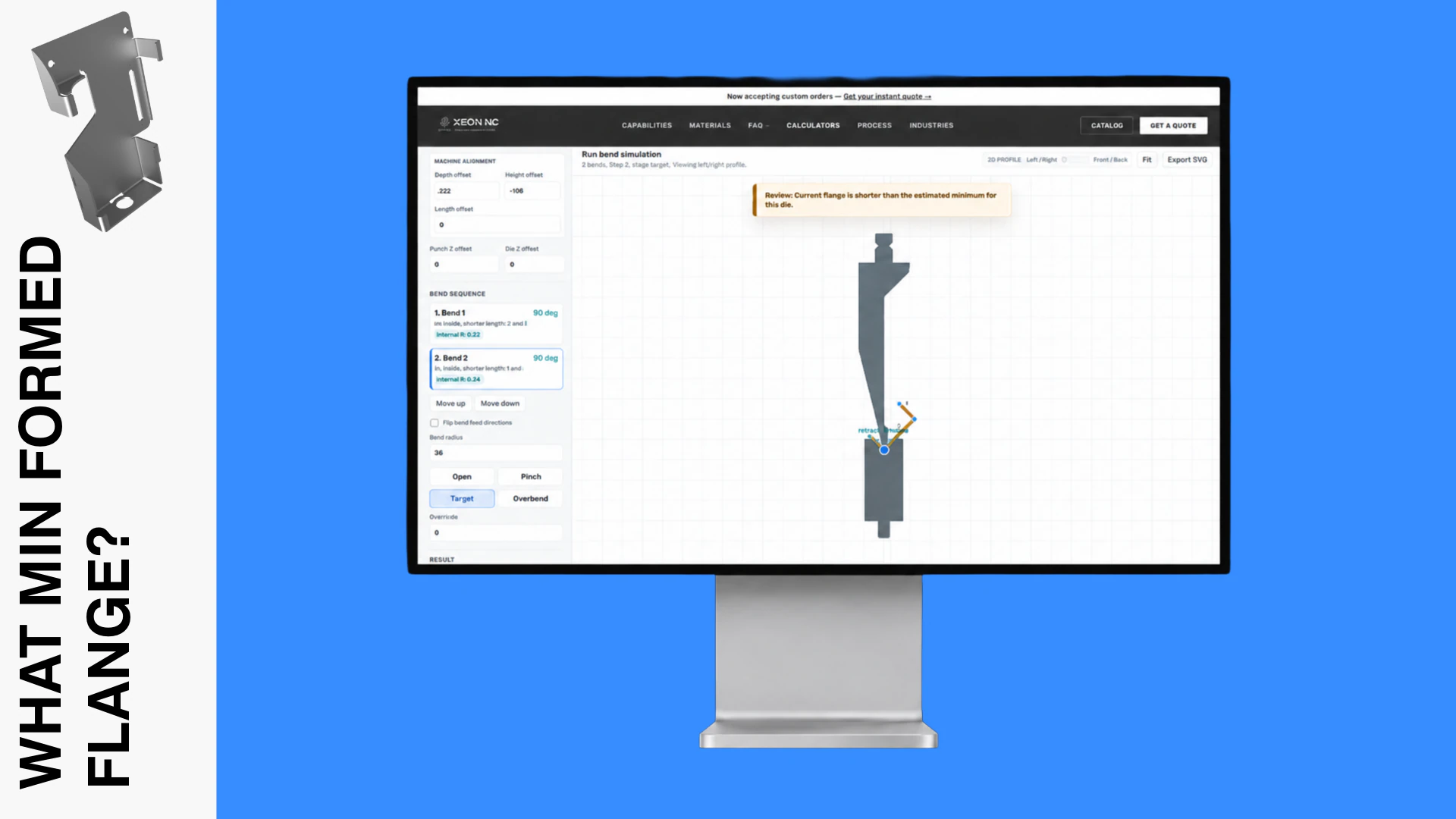
A flange also has a physical minimum. During air bending, enough material must sit across the die shoulders to remain controlled. As a design starting point, use a formed flange around 4 times the material thickness. The actual minimum is calculated from V-opening, angle, inside radius, and the geometry of the part.
Early-design heuristic / not a tooling release
START WITH FLANGE ≥ 4T
T = material thickness. Xeon NC validates the final minimum against the die and angle used for production. Shorter flanges may be possible with alternate tooling; some geometries need more.
Constraint / flange supportThe right question is not whether the bend line exists. It is whether the flange remains supported by the selected die throughout the stroke.
04 / Dimensional Tolerances
What the numbers on the drawing mean.
Tolerances are always symmetrical relative to the nominal dimension. A leg called out at 40 mm with a ±0.3 band is accepted anywhere from 39.7 to 40.3. There is no one-sided allowance and no implied bias toward the nominal.
Which letter governs a given dimension depends on how many bends sit between the two faces being measured. Every additional bend contributes its own angular and positional error, so a span measured across two bends carries a wider band than a single leg measured off one.
Dimension keyMeasured fromGoverned by
S
Sheet thickness, as supplied. Feeds the bend deduction and the inside radius, so it drives every other number in this table.
Material
A
Leg length. The distance from an outside face to the first bend, measured on a single formed leg.
One bend
B
Second leg or upstand height. Measured on the opposing flange of a channel or hat.
One bend
C
Span across two bends, such as the base of a hat section or the inside width of a channel.
Two bends
D
Offset dimensions on a Z-bend. Height, step, and overall length are all governed together because the two bends oppose each other.
Two bends
E
Included bend angle. Verified in-process by the ACB laser rather than assumed from the program.
Angle
F
Angle precision over length. The permissible angular drift along a bend line, expressed per unit of bend length.
Reading the diagramsEvery dimension shown is symmetrical about nominal. Letters repeat within a profile where the same tolerance rule governs more than one feature — both upstands of a channel are A because each is formed off a single bend. On the offset, F is the angle of the web against the horizontal datum, not a length.
Tolerance basis / always symmetrical
± RELATIVE TO NOMINAL
Angle precision (E): see table — ±0.5° standard, held closed-loop by the ACB laser on the TruBend 5170. Leg length (A, B, C, D), per setting: see table — the band widens with sheet thickness and with the number of bends spanned.
Tolerances apply per setting. A part re-gauged between operations stacks a new band on each setting rather than carrying one band across the whole part.
Units
S — sheet thickness
A
B
C
D
E — angle
F — precision
.118″up to 3 mm
±.008″± 0.2 mm
±.016″± 0.4 mm
±.031″± 0.8 mm
±.020″± 0.5 mm
± 0.5°
15′/100 mmper 3.937″ of bendper 100 mm of bend
.157″4 mm
±.012″± 0.3 mm
±.024″± 0.6 mm
±.047″± 1.2 mm
±.024″± 0.6 mm
± 0.5°
15′/100 mmper 3.937″ of bendper 100 mm of bend
.197″ – .236″5 – 6 mm
±.016″± 0.4 mm
±.031″± 0.8 mm
±.063″± 1.6 mm
±.031″± 0.8 mm
± 0.5°
15′/100 mmper 3.937″ of bendper 100 mm of bend
.315″8 mm
±.020″± 0.5 mm
±.039″± 1 mm
±.079″± 2 mm
±.039″± 1 mm
± 0.5°
15′/100 mmper 3.937″ of bendper 100 mm of bend
.394″10 mm
±.031″± 0.8 mm
±.063″± 1.6 mm
±.126″± 3.2 mm
±.063″± 1.6 mm
± 0.5°
15′/100 mmper 3.937″ of bendper 100 mm of bend
Checker platetextured stock
.079″2 mm
—
—
—
± 1.5°
—
Hemmingfolded edge
±.039″± 1 mm
0 – 0.5 × Sof sheet thickness
—
—
—
—
Using the tableRead down to your sheet thickness, then across to the letter you are dimensioning. F is angular drift along the bend line and is quoted per 100 mm of bend length, so a longer bend carries proportionally more. Inch equivalents are converted from the millimetre values, which govern.
05 / Software Before Pressure
Preflight the geometry. Then form the part.
Our bending check turns a formed 3D model into a set of physical questions before material reaches the press brake.
01
Recognize the bends.
Read bend direction, target angle, radius, adjacent flanges, and the relationship between each formed feature.
02
Assign material and tooling.
Match alloy and thickness to an available punch and V-die, then calculate the flat using the bend deduction for that process.
03
Check the bend-affected zone.
Flag holes, slots, text, and cut edges that may stretch, ovalize, or tear as material flows through the bend.
04
Prove the movement.
Simulate part-to-tool, part-to-machine, and part-to-part clearance as the sheet rotates through each stroke.
05
Prove the sequence.
An early bend can block a later one. The sequence must preserve a usable backgauge surface and a path into and out of the tooling.
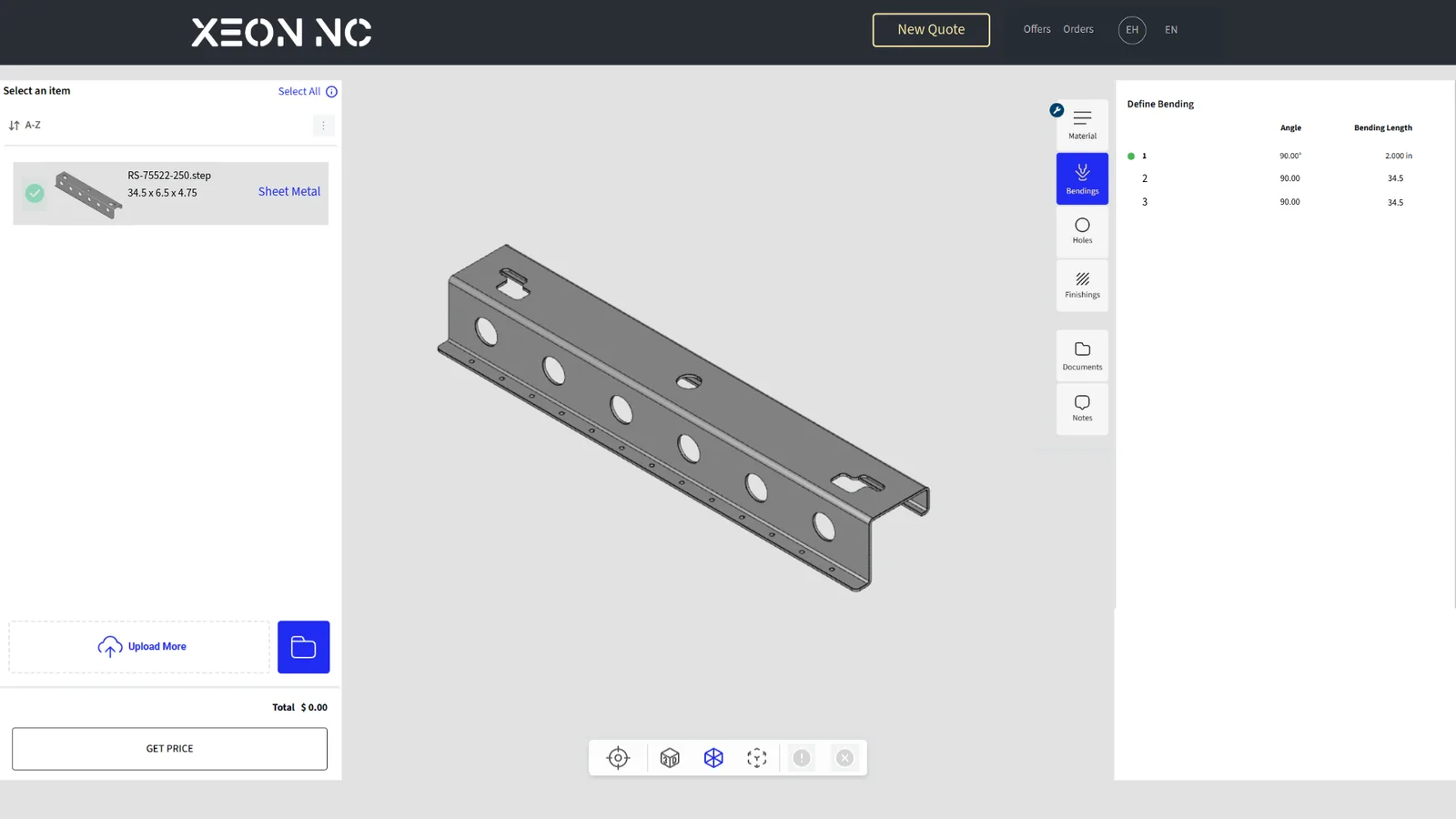
Digital inspectionThe uploaded formed model exposes the bend set before the order is released. The goal is not simply to quote a shape; it is to understand the manufacturing state behind it.
06 / Design Rules
Five rules for parts that bend cleanly.
Good sheet-metal geometry gives the material room to move and the tooling room to work.
01
Send the formed STEP.
Do not make an unsupported flat pattern the source of truth. Send the final 3D intent; we develop the blank around the actual tooling and bend deductions.
02
Give the die enough flange.
Start around 4T in early design. Final support depends on V-opening, bend angle, radius, and the position of nearby cutouts.
03
Use a realistic inside radius.
A 1T inside radius is a common starting point for ductile sheet, but alloy and temper matter. Hard materials such as 6061-T6 often need a substantially larger radius and favorable grain direction to avoid cracking.
04
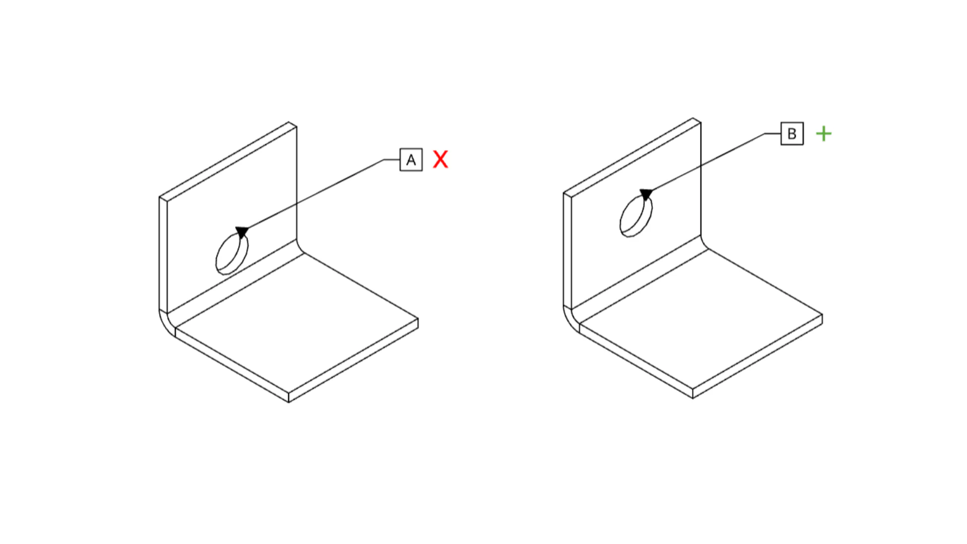
Move holes away from the bend.
A useful starting point is hole edge to bend centerline ≥ inside radius + 2T; use more room for harder alloys. Features inside the deformation zone can stretch or turn oval.
05
Relieve terminating bends.
Where a bend stops at an edge, slot, or adjacent wall, add a relief that gives displaced material somewhere to go. This reduces tearing, bulging, and unintended distortion.
Bend-affected zoneThe bend changes more than the line. Material on the outside stretches, material on the inside compresses, and nearby holes can distort with it.
07 / Closed-Loop Forming
What the machine corrects—and what the design must correct.
TRUMPF ACB angle measurement lets the press brake respond to the material in front of it. It does not make impossible geometry possible.
During the stroke, non-contact optics measure both flanges and compare the actual angle with the target. The control can compensate for springback and material variation before the ram returns. That makes angle control more consistent across prototypes, batches, and material lots.
Closed-loop machine control
ACB can correct
Springback during the active bend
Small material-lot and thickness variation
The ram depth needed to reach the programmed angle
Repeatability when the flanges provide a valid optical surface
Design and preflight
Geometry must correct
A flange too short for the die
A hole or slot inside the bend-affected zone
Punch, machine, or part-to-part collision
An unrealistic radius, cracked material, or impossible sequence
Measurement is most effective when both flanges present enough clean surface to read. Very short flanges, perforations at the measurement zone, or unusual geometry may require another verification strategy. The design still has to create a bend the machine can physically see and execute.
08 / The Mission
Any angle, any flange—inside the physical envelope.
The purpose of preflight is not to say no. It is to convert uncertainty into a solvable manufacturing state.
A useful bending platform should let a designer explore complex formed geometry without already being a press-brake operator. It should reveal the same constraints a production engineer sees: the radius that an alloy can survive, the die that can support the flange, the tool that can clear the box, and the sequence that keeps the last bend reachable.
When those constraints are visible early, prototypes become faster, revisions become cheaper, and production becomes predictable. The result is not just a bend that matches an angle. It is a complete part whose geometry survived contact with the real world.
The goal is not unlimited geometry. It is legible geometry.