Now accepting custom orders — Get your instant quote →
Overview
How It Works
Hardware Types
Materials
Specs
Design Tips
PEM Self-Clinching

HARDWARE

INSERTION.

Permanent fasteners pressed into your sheet metal parts at the factory — PEM nuts, studs, standoffs, and blind standoffs that can't be removed, stripped, or shaken loose.

5
Hardware types
40+
Thread sizes
SAE+M
Inch & metric
PEM Hardware Insertion at Xeon NC
01 — How It Works

PRESSED IN.

PERMANENTLY.

PEM self-clinching fasteners work by forcing a serrated or knurled shank into a precision-punched hole under controlled press force. The displaced metal flows into the clinching ring, creating a permanent, non-removable mechanical lock — no adhesive, no welding, no clips.

01
Punch the Hole
A precision CNC-punched or laser-drilled hole is made to the exact diameter required for each fastener size. Hole tolerance is critical — ±0.002″ is standard.
02
Position the Fastener
The PEM fastener is seated (installation side down) in the hole — it locates itself. No fixturing required. The anvil plate holds the sheet from below.
03
Press to Clinch
A controlled press load forces the clinching shank into the sheet. Metal displaces into the serration groove, locking the fastener permanently in shear and pull-out.
04
Inspect & Continue
Each insertion is visually checked for flush seating and correct clinch. Parts then proceed to bending, finishing, or shipping — hardware arrives ready to assemble.
02 — Hardware Types

FIVE TYPES.

ONE ORDER.

Mix and match hardware types across the same part — specify what you need in your drawing and we install it all in-house before shipping.

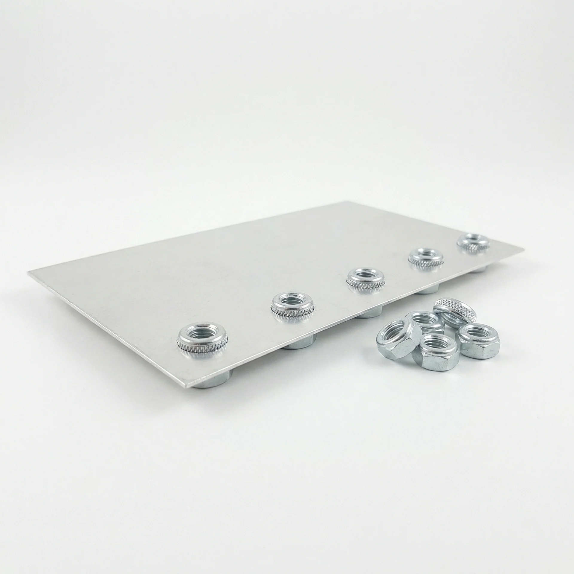
PEM Nuts
// S & SP Series
PEM Nuts
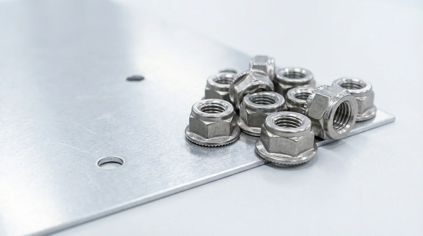
Standard self-clinching nuts providing permanent internal threads. Body protrudes slightly on the installation side. Available #4-40 through M6 in steel and stainless.
Size Chart →
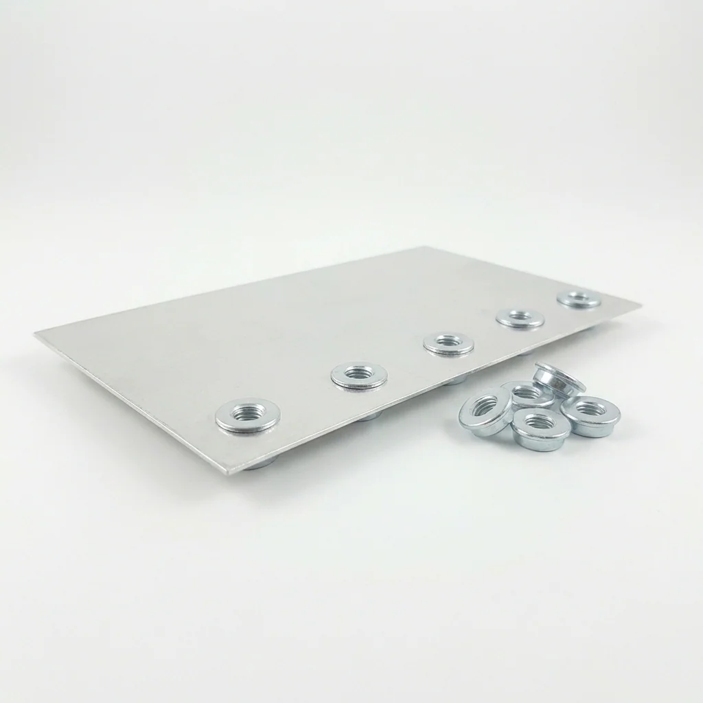
PEM Flush Nuts
// F Series
PEM Flush Nuts
Flush on both faces after installation — no protrusion. Required for stacking panels or flat mating surfaces. Steel only.
Size Chart →
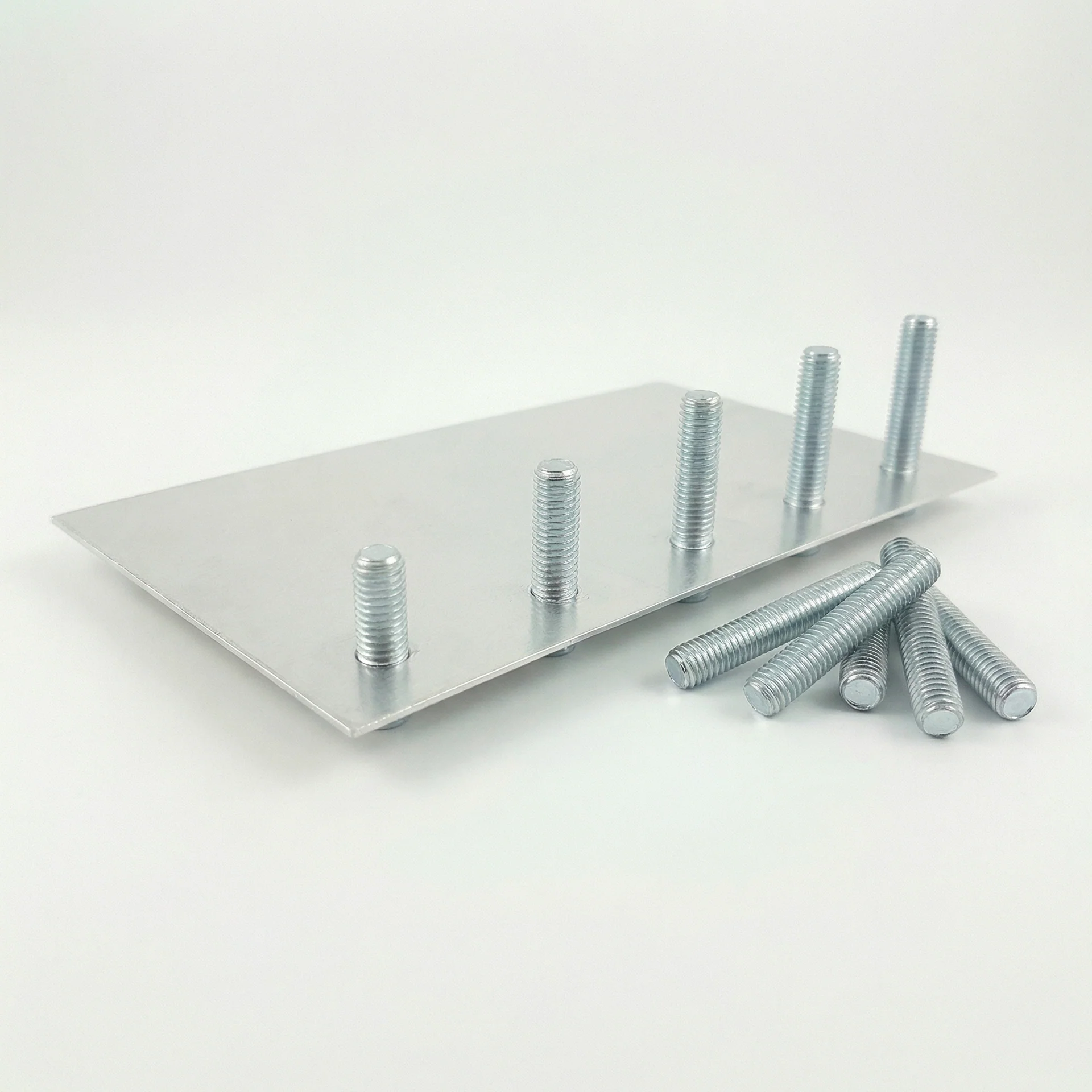
PEM Studs
// FH & FH4 Series
PEM Studs
Permanent external threaded posts for attaching PCBs, brackets, or panels with a nut. Multiple protrusion lengths available.
Size Chart →
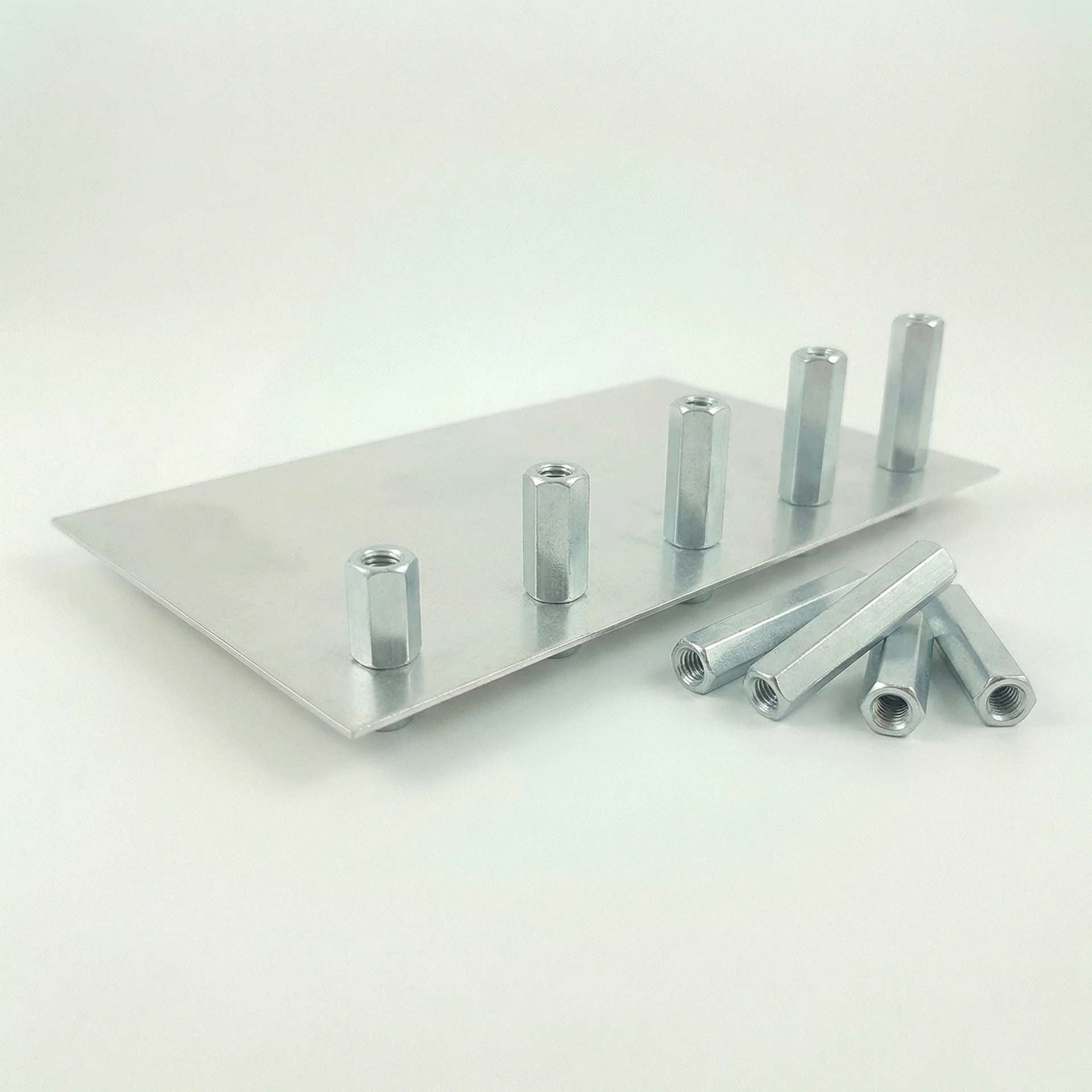
PEM Standoffs
// SO & SO4 Series
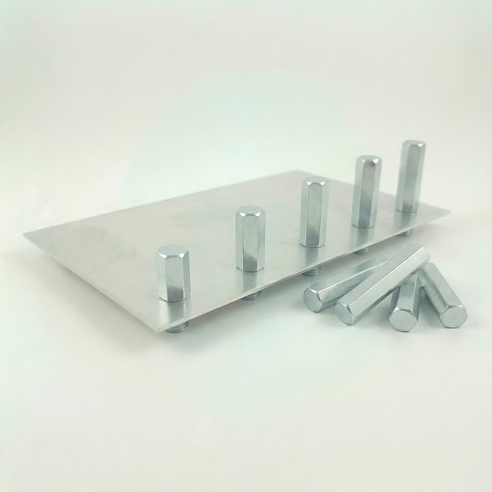
PEM Standoffs
Through-threaded hex spacers for fixed-height PCB mounting and panel spacing. Both ends accept a bolt. Available in a wide range of heights.
Size Chart →
PEM Blind Standoffs
// BSO & BSO4 Series
PEM Blind Standoffs
Closed-end standoffs — bolt enters from one side only. Protects threads from debris and liquids, provides a clean exterior face.
Size Chart →
View Full PEM Hardware Catalog with Size Charts →
03 — Materials

STEEL OR

STAINLESS.

PEM hardware is available in two material grades to match your sheet metal and application environment. Choose based on corrosion resistance and galvanic compatibility.

  • Carbon Steel (zinc-plated, suffix -ZI) — standard choice for steel sheet; economical, strong, RoHS-compliant finish
  • Stainless Steel 303/304 (suffix -SS) — required for aluminum or stainless sheet to prevent galvanic corrosion; suitable for harsh environments
  • Install into Aluminum 5052 & 6061 — always specify stainless PEM to avoid dissimilar-metal corrosion
  • Install into Steel A1008 / A36 — steel ZI hardware standard; stainless available on request
  • Install into Stainless 304 / 316 — stainless PEM required throughout
  • Minimum sheet thickness: 0.040″ (22 ga) for #4-40 — thicker required for larger thread sizes
PEM hardware materials
303/304 STAINLESS
ZINC-PLATED STEEL
04 — Specifications

TECHNICAL DATA

Hardware Types
PEM Nuts · Flush Nuts · Studs · Standoffs · Blind Standoffs
Thread Range (Inch)
#4-40 · #6-32 · #8-32 · #10-32 · ¼-20
Thread Range (Metric)
M2.5 · M3 · M4 · M5 · M6
Hardware Material
Carbon Steel (zinc-plated, ZI suffix) · Stainless Steel 303/304 (SS suffix)
Size & Material Chart
Hardware size chart — hole size and part number for every fastener, checked against the gauge and alloy you picked
Compatible Sheet Materials
Aluminum 5052 / 6061 · Steel A1008 / A36 · Stainless 304 / 316
Min Sheet Thickness
0.040″ (22 ga) for #4-40 · Up to 0.093″ for M6 — varies by thread size
Hole Tolerance (Punch)
±0.002″ required for proper clinch — CNC punched or laser-drilled preferred
Install Sequence
Hardware installed before bending (where possible), and always before powder coating or anodizing
Lead Time
Hardware adds no lead time to standard 3–5 day production cycle
File Requirements
Specify PEM part number and installation side on drawing. Include punched holes in DXF or STEP. Hole size per type — see hardware catalog for exact dimensions.
05 — Design Tips

DESIGN IT

RIGHT.

A few rules on your drawing prevent the most common hardware-insertion problems before they happen.

  • Call out the PEM part number: include series, thread size, and length (for studs/standoffs) on the drawing — e.g., "INSTALL S-632-1ZI THIS SIDE"
  • Specify the installation side: the fastener body or clinching feature always protrudes on the installation side — make sure you have clearance there
  • Match hole diameter precisely: too large = no clinch; too small = won't seat. Use the hole size in our hardware catalog — don't guess
  • Edge distance: keep hardware center ≥ 2× hardware OD from any part edge or bend line
  • Bend sequence: hardware installed before bending wherever geometry allows — flag any exceptions in your notes
  • Anodize / powder coat: all hardware installed first; finish is applied after — no coating will be inside the threaded bore for standard installation
  • Stainless in aluminum: always use -SS (stainless) PEM in aluminum sheet — never steel ZI hardware against aluminum
PEM standoff design reference
INSTALLATION SIDE
THREAD ENGAGEMENT
Ready for Production

QUOTE YOUR PARTS

Upload your DXF and call out your PEM hardware. We install it all in-house before shipping — no extra steps, no separate vendors.

Get a Quote Full PEM Catalog →