01 / Shop footage
Built for clean, confident bends.
5052-H32 combines strength with excellent formability, making it a dependable choice for tight bends, multi-sided enclosures, brackets, covers, and other formed sheet metal parts.
Thicknesses are the decimal we actually stock and cut. Converting from a gauge number? See the sheet metal gauge chart — the gauge scale differs by metal.
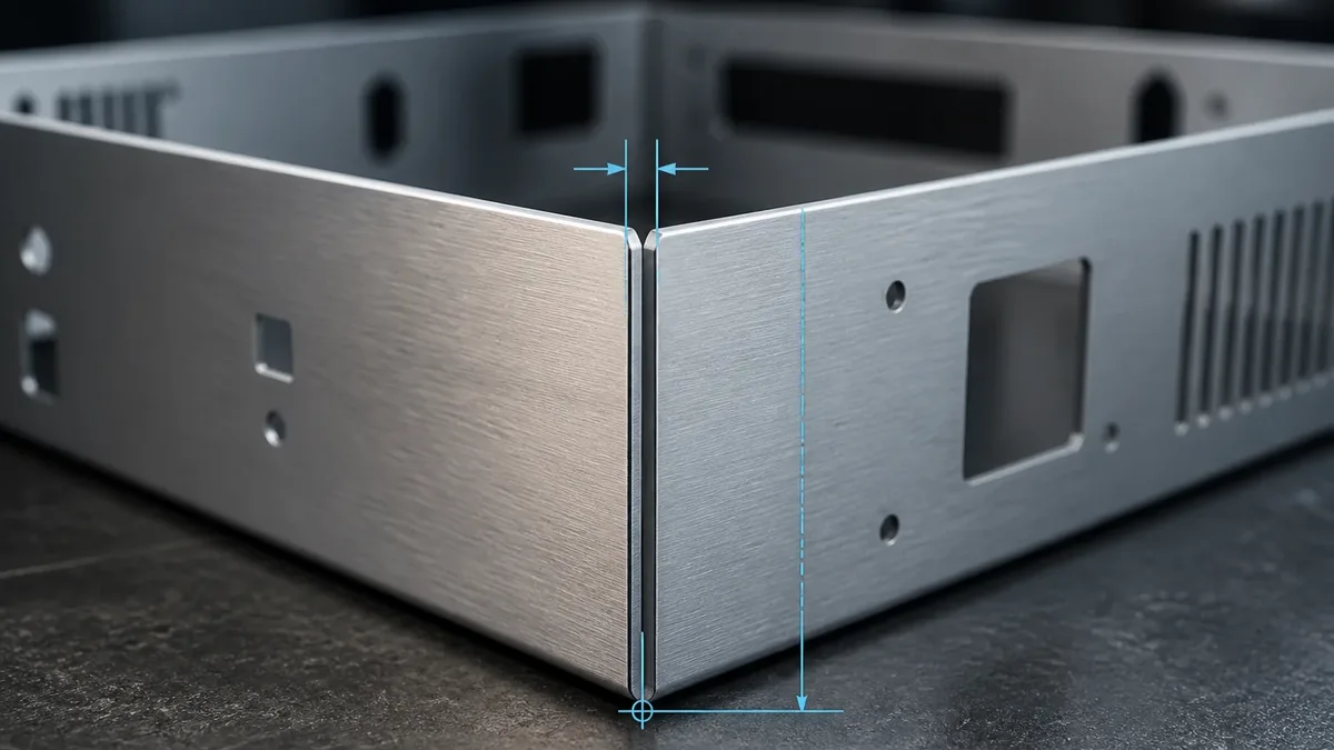
Thickness minus half the 90° bend deduction for this gauge’s production die, plus 0.015″ of forming clearance. Floored at 0.010″. The highlighted row above is that number for the thickness you selected.
View article →Reference values per the listed specification — a basis for design comparison, not guaranteed minimums for certification work. Material certs available on request.
A closer look at the alloy we rely on for formed enclosures, corrosion-resistant assemblies, and clean finished parts.
5052-H32 combines strength with excellent formability, making it a dependable choice for tight bends, multi-sided enclosures, brackets, covers, and other formed sheet metal parts.
Its magnesium-rich chemistry gives 5052-H32 outstanding resistance to saltwater, weather, and many industrial environments without adding the weight or cost of stainless steel.
5052-H32 accepts anodizing and powder coating beautifully, helping visible panels, housings, and production assemblies hold a clean, consistent appearance from prototype through volume.
A closer look at a versatile structural aluminum alloy valued for its strength-to-weight balance, machinability, and dependable fabrication performance.
6061-T6 delivers an excellent balance of strength, low weight, and machinability for structural brackets, fixtures, frames, plates, and precision aluminum components.
6061-T6 supports accurate, repeatable fabrication for components that need structural rigidity, low weight, and dependable dimensional performance from prototype through production.
Precision laser cutting produces repeatable 6061-T6 profiles with accurate geometry and clean edges, creating a strong starting point for machining, finishing, and final assembly.
Pickling removes mill scale and oil protects the exposed surface, giving structural hot-rolled steel a cleaner starting point for laser cutting, forming, welding, paint, and powder coat.
A36 and A1011 hot-rolled P&O retain the strength, weldability, and economy of hot-rolled steel while providing a cleaner surface for fabrication and downstream finishing.
A production-representative bend shows how A36 hot-rolled P&O moves through the press-brake operation, including the local deformation that develops around a hole placed close to the bend.
A closer look at the clean pickled-and-oiled surface and the practical formed geometry this material supports across structural brackets, weldments, frames, and production assemblies.
Two laser-cut panel strategies, one material system: perforation controls openness and airflow, while larger cut geometry turns the weathering surface into architecture.
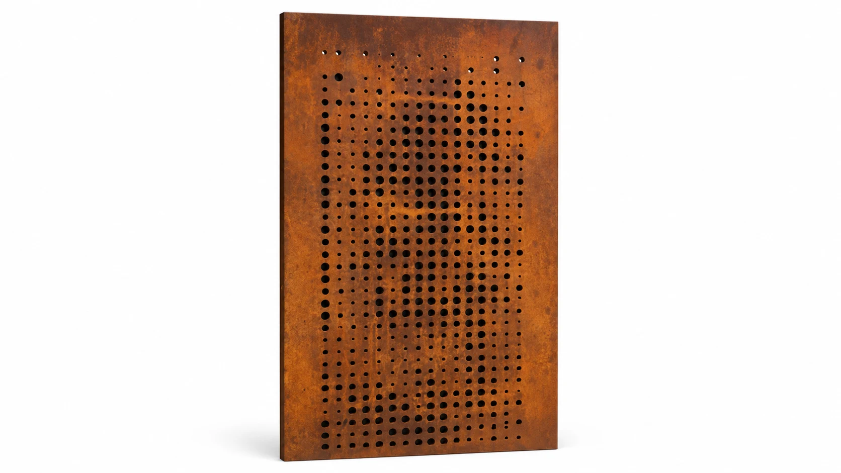
A variable field of laser-cut holes gives the Corten panel controlled transparency, airflow, and visual depth while the protective patina supplies the finished exterior surface.
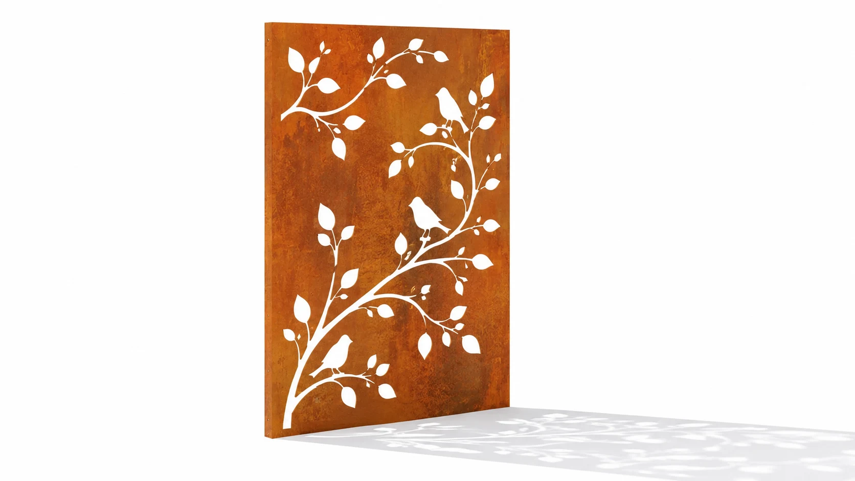
Large botanical cutouts demonstrate the design freedom of fiber-laser processing while the A588/A606-4 weathering surface develops the color and character that make Corten distinct.
A closer look at economical hot-rolled structural steel for thick parts, weldments, brackets, frames, and components headed to blasting, paint, or powder coat.
A36 and A1011 hot-rolled steel provide dependable strength, weldability, and forming performance for structural brackets, machine frames, supports, and heavy-duty fabricated parts.
Hot-rolled mill-finish steel is a cost-effective choice when strength, thickness, and production efficiency matter more than a cosmetic raw surface.
The as-rolled surface protects parts during handling and works well for weldments or components that will be blasted, painted, powder coated, or otherwise finished after fabrication.
A closer look at smooth, tightly controlled cold-rolled steel for precision enclosures, panels, brackets, and powder-coated production assemblies.
A1008 cold-rolled steel combines tight thickness control with excellent formability, supporting accurate bends and repeatable geometry in enclosures, panels, covers, and brackets.
The uniform surface and consistent gauge of A1008 help produce clean laser-cut profiles for detailed features, production blanks, and parts headed directly into forming.
Cold-rolled A1008 provides a clean base for powder coating and paint, helping visible housings and production assemblies achieve a consistent finished appearance.